Download
1 / 17
180 likes | 276 Vues
My experience at Commissioning. matteo. Matteo Volpi. Fiber tests. Matteo Volpi. Why to test fibers. Slide 1. Fiber Attenuation measurements - Failure to deliver the necessary light level by either TTC or Glink fibers will prevent the data taking from the associated Tile module.

E N D
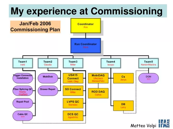
My experience at Commissioning matteo Matteo Volpi
Fiber tests Matteo Volpi
Why to test fibers Slide 1 • Fiber Attenuation measurements - Failure to deliver the necessary light level by either TTC or Glink fibers will prevent the data taking from the associated Tile module. • Fiber Length measurements – Uncertainty on the fiber length will result in for TTC – uncertainty on arrival time of the clock and control commands => BC-id and TOF The Tile studies from the TBs proves that while the fiber length is well controlled the resolution of the time measurement from the Tile can be as good as (0.7-1.0)nsec.
TESTs Slide 2 • Fiber Attenuation measurements, were done for 850nm (ROD wavelength) and 1300nm (TTC wavelength) with the LED Source/Meter • Fiber Length measurements done with the OTDR (Optical Time Domain Reflectometer) • All data went into the QCsheets linked to the wikipage of commissioning team 3
Attenuation tests done with LED Source/Meter (OLS-5 and OLP-5) Patch Panel USA15 Meter (end of the fiber) Source Tile Fibers ~ 90 m ( LC/PC and SC/PC connectors) Fiber ~5 m (SC/PC and LC/PC connectors) Test SETUP Slide 3 Length tests done with OTDR (Optical Time Domain Reflectometer) Patch Panel USA15 Finger patch panel (SD) OTDR Tile Fibers ~ 90 m ( LC/PC and SC/PC connectors) Fiber ~2 m SM fiber (FC/APC and FC/PC connectors) Fiber ~5 m (SC/PC and LC/PC connectors)
Possible future setup Gerolf Schlager Slide 4 Reminder: minimum level into TileCal Front-End Electronics at the SD patch panel is -15 dBm Patch panel SINGLE MODE MULTI MODE (laser source) 1:16 TTCex Optical attenuator TTCoc TileCal Front-End (Optical Splitter 16 output at -13 dBm ) 8 outputs USA15 UX 15 Max. possible loss from TTCoc to TileCal Front-End 2dB (safety margin 0,5 dB) Acceptance level 1,5 dB in Multi Mode fibers (at the moment we use MM fibers) Acceptance level 3 dB in Single Mode (TTCoc and TTCex tested with SM fiber that has 1.5 dB moreof tolerance). This must account for: -Losses in patch panel -Losses in connectors -Losses in the fibers
LBA EBC EBA LBC Nominal Patch Panel Loss (USA15) Slide 4 Patch Panel Nominal Value for each channel are known
Connector in USA15 Patch Panel One big cable for each sector is spliced in 6 cables of about 20 meters before the end of the fibers in the module. We have some times Problems with the splice box ( see the next slides ) We cleared and checked the connectors a many times. All the fibers components were found to be very sensible to the dust, etc Slide 5
Super Drawer Patch Panel Slide 6 TTC & ROD fibers
Measurement I :The Attenuation Slide 7 Sector 9 Side A Expected value of attenuation: Nominal loss in the Patch panel + Losses in the connectors + Loss inside the fibers: ~0,06dB at 1300 nm for ~ 100 m ~0,2dB at 850 nm for ~ 100 m Accuracy of measurement is 0,3dB from stability of the measurement by LED Source/Meter (that includes variations due to connector) • High loss for connector # 5 (spare) at A side • Out of specification using SM fiber to connect TTCex and TTCoc: attenuation more than ~3dB • High loss for connector #19 (RO) at A side • Out of specification: attenuation more than ~ 1.5dB using MM fiber to connect TTCex and TTCoc • Both have to be exchanged
Int. board inside the SD Start SD Patch Panel Length Ghost Normal response Patch Panel USA15 Finger patch panel (SD) OTDR Tile Fibers ~ 90 m ( LC/PC and SC/PC connectors) Fiber ~2 m SM fiber (FC/APC and FC/PC connectors) Fiber ~5 m (SC/PC and LC/PC connectors) Measurement II :Length of the fibers Slide 8 With the OTDR we measure the length of the fibers. Speed is 4,9 ns/m ( 2.1x10^8 m/sec) Length resolution (OTDR) < 1cm
Measurement II :Length of the fibers Slide 9 Length for 36 fibers of sector 5 A Side We see the long and the short fibers within the pack, as expected When the finger are connected we can measure the length of the fiber inside the Super Drawer, the average is 1,27 m (Patch panel to Interface board) All the data are stored in the data base. These Measurements are important for the timing. In advance we confront the limitation of these machines, the OTDR and LED Source/Meter
More Information Slide 10 What can be detected with OTDR only: -length of the fibers -the loss in extreme damages e.g. bending, breaking.( I try the test with broken fibers) -some effect in the patch panel connectors. -Also when the fingers are already inserted in the SD: we can check the connectors we can measure the length of the fibers inside the SD The good resolution of the OTDR (<1cm) is fundamentally for the time reconstruction, necessary for the system as the TOF. What can be detected with LED Source/Meter only: -the attenuation in the fibers and in the patch panel connectors -of course the loss in extreme damages e.g. bending, breaking What can be seen by both systems: -some effect in the patch panel connectors - the loss in extreme damages
End of the fiber About 16m Example of OTDR Test for the Bad Fibers Slide 11 With the OTDR we checked the bad fibers analyzed with the LED Source/meter We can see a big reflection at about 16 meter before the end of fibers in both cases. The fibers are in the Sector 5 A Side and are: -Module 17 TTC fiber, color white, channel 20 in the Patch Panel. -Module 20 Spare fiber, color orange, channel 35 in the Patch Panel. The problem is in the same position for both fibers located in two different cables.
New test with the OTDR after to check the bad fibers in the splice box Channel 20 The reflection 16 meter before the and disappear. With LED Source Meter we measure again the attenuation is: Channel 35 : 0,60 dB at 1300 nm 1,08 dB at 850 nm Channel 20: 0,49 dB at 1300 nm 0,89 dB at 850 nm Before we don’t have communication in these channels Red line=old measure Blue line=new measure Channel 35 Red line=old measure Blue line=new measure Conclusion: the fibers are reaper. Slide 12
Int. board inside the SD Start SD Patch Panel Length Patch Panel Ghost Normal response: no gap Loss after P.P. Fiber Tile Some effect seen with the OTDR Slide 13 Normally with the OTDR we see the back reflection signal from the connectors. During the measurement of the length we see this effect : -Loss in the connector in the patch panel : Normally this loss is much smaller than the OTDR sensitivity. After to open and clean the connector the loss disappear.
Conclusions Slide 14 At the moment we have checked the Sector 5,7,9,11 and 13 with LED Source/Meter and OTDR. I was the responsibile of the measurements and the OTDR tests. My conclusion is: With the OTDR we can see some effects that belong to the finger: -problems in the connector in the SD -back reflection in the connector -the loss in extreme damages e.g. bending, breaking We need both instruments: the LED Source/Meter to measure the attenuation and the OTDR to measure the length of the fibers, because the OTDR can not measure the attenuation of the fibers. Before leaving I taught Valencia team (now assigned to the tests) to use the machines. Future plan: Check the next sector and if there are the problems, change the damage fibers and check the bad connectors.