Download
1 / 112
1.13k likes | 1.25k Vues
EMS1 Elements, Materials and Structures Drill: Identify the four states of matter. OBJECTIVE: Compare and contrast the atomic make-up of elements as we read info packets.

E N D
EMS1 Elements, Materials and StructuresDrill: Identify the four states of matter OBJECTIVE: Compare and contrast the atomic make-up of elements as we read info packets.
The four sates of matter areSolid, Liquid, Gas’ Plasma(see power point FourStatesOfMatter –H drive Engineering)In your notes write the following three questions.When did the ‘Industrial Revolution’ (IR) occur in the United States? What factors contributed to the IR? Identify two positive and two negative consequences of the IR.
EMS1 Elements, Materials and Structuresp 29, pp. 228 - 229 When did the ‘Industrial Revolution’ (IR) occur in the United States?What factors contributed to the IR?Identify two positive and two negative consequences of the IR.
EMS1 Elements, Materials and StructuresAnswers p 29, pp. 228 - 229 When did the ‘Industrial Revolution’ (IR) occur in the United States?The IR occurred about 1750 to 1900. p. 29What factors contributed to the IR?Factors contributing to the IR included new energy sources, factories, and changes in manufacturing processes. P.228Identify two positive and two negative consequences of the IR.
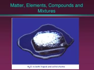
Technology is the use of knowledge to create tools to make work easier and improve life.One of the areas of knowledge most applied is Science.Pages 575 – 577 deals with matter and properties of materials.As you read the short section be sure to define MASS, DENSITY, ELEMENTS, and COMPOUNDS, then briefly explain the seven properties of materialsThis should act as a introduction or review of basic chemistry.
Pages 575 – 577.MASS – measure of the amount of matter in an object DENSITY –measure of mass per unit of volume ELEMENTS – substance containing only one kind of atom. COMPOUNDS – when more then one element combine to form another substance (possibly quite different then ingredients).
properties of materialsSENSORY – those we can see, hear, taste, or feelOPTICAL – how a material reacts to lightTHERMAL – how a material reacts to heatELECTRICAL – whether a material is a conductor, insulator, or in between (semiconductor)MAGNETIC – how a material reacts to a magnetCHEMICAL – include if a material will rust (oxidize) or dissolve materials MECHANICAL – how a material reacts to forces*Please turn to page 251 to identify and define MECHANICAL PROPERTIES
Mechanical properties include:DUCTILITY – ability to be formed and reformed ELASTICITY – ability to regain shape after being pulled or pushed HARDNESS – ability to resist denting and scratchingPLASTICITY ability to be pressed, molded, or stretched to a new shape that can be retainedSTRENGTH –ability to resist forces such as compression and tension*Please turn to page 349 to identify and describe common building materials.
Create an experiment data sheet with the following info:Problem:Goal:Constraints:Assessment criteria:Tower info: Tower 1 Tower 2 Tower 3Books supported .Sketch of Tower_____________________________.
As we study the use of materials in technology it is important to understand how the shape of materials effect strength. We have 35 textbooks in the class. We need to store the textbooks in a creative way. To demonstrate Hereford HS students extraordinary analytical and creative minds we are going to create a stand to stack the books on top of. The stand will be made only of one sheet of paper and 3 inches of masking tape. No other materials or equipment may be used (except a ruler for measuring). The bottom book must be supported at least 3 inches off the top of the table. Students will have three attempts at making their support system. The students may use one sheet of paper during each construction period. The first two construction periods will be five minutes. The third ten minutes. The system must be free-standing
Students are expected to use one sheet of paper to design their first tower. Students should sketch their tower as they complete it and document the results. After five minutes we will construct a second support system. The design of this system should utilize information from the original tower. The third tower will be the final tower that results from information obtained during construction of first two.Students All earn one point for each book supported. The points from each session will be totaled. >33 = A, 33 – 30 = B, 29 – 26 = C. The best performing tower from each session will earn that team 4 bonus points.
EMS 2 - OBJECTIVE: Analyze the connections of chemistry with Metallurgy as we create not sheet while watching ‘History of Metals’.Drill: Very briefly explain what modifications you made to the sheet of paper to allow it to support books
As we complete video ‘History of Metals’ continue your notes identifying important developments of the metals industry and important connections between Chemistry and Metallurgy.You should already have information on the copper, bronze, iron, steel and gold as well as what the base elements are that make up the various metals.
Before we start video lets review Power Point SuggestionsPower Point Requirements- Power Point should be designed to accompany your 3 – 4 minute oral presentation of your topic investigation.- Presentation should include Introduction, Body, Conclusion- Power Point should consist of 6 – 12 slides.- Slides should support what you are discussing (Key points)- Slides should be interesting, can include pictures, diagrams, or graphs, and aid in discussion.- Slides should not be busy
Power Point Slide SuggestionsINTRODUCTION– Your nameYour Topic Investigation Brief Introduction be sure all fonts matchpictures should support topic
INTRODUCTION / BODY– Brief overviewhighlight key concepts you will discuss (list) Brief Introduction be sure colors showpictures should support topic
BODY (1)– First Talking PointSpelling is impotantIS FONT VISIBLE?DON’T MAKE THE SLIDES TOO BUSYFOCUS ON KEY TALKING POINTS
BODY (2)– Second point of emphasisDon’t forget the power of graphs and charts
BODY (3)– Each presentation should have at least three talking points. You’ve had since August to work on this Topic Investigation. Your content should demonstrate the amount of time given to work on this. The power point slide should be kept interesting and simple. Don’t try to put too much information on one slide. It is better to have more then one slide when presenting a lot of information. Be sure there is a smooth flow between the slides (rhythm)
CONCLUSIONSummarize presentation by highlighting key points.What was your conclusion?
EMS 3 - OBJECTIVE: Evaluate how shape effects strength of a material by creating a comparison chart as we complete a set of experiments.Drill: Identify modifications you made to the sheet of paper that resulted in an increased strength to compression.NOTE: WHEN PERFORMING THIS LAB It will be much more effective to (1) read over entire instructions as a class. (2) Break into groups with each group responsible for testing and recording results of one shape. (3) Share results in class discussion allowing students to complete table during discussion.
Before we begin this lab experiment it will be important to review some information in Technology Engineering and Design text.Please obtain a copy of the text (you may share with the person next to you) and turn to page 391
In your notes sketch the four types of forces on page 391Then turn to page 395, sketch and label FIGURE 20-4 in your notes
Turn to page 397, identify and briefly describe the types of bridges.Take a moment to review the types of dams on pages 398 and 399.Also take a moment to read Science Application on page 403
Also take a moment to read Science Application on page 403Finally answer Thinking Critically questions 1 and 2 on page 404
During classEMS1 (2 classes ago) we created a set of three ‘stands’ that were to support the greatest number of books three inches off the table.Each ‘stand’ was to use information obtained during the construction of the previous stand.The greatest success was achieved when we tore the paper into a series of equal length sheets then rolled those sheets into tubes. Each tube was layered to increase its strength.During class today we will further investigate how shape effects strength as we perform a set of experiments
Each group will consist of two members.Teams will complete shape tests for one of the following:A) ‘Beam Assembly’ – Determine what shape Beam your group is responsible for. Construct that shape Beam and complete ‘failure test’. Be sure to weigh structure.B) ‘Column Assembly’ – Determine what shape Column your group is responsible for. Construct that shape Beam and complete ‘failure test’. Be sure to weigh structure
A total of 13 tests are to be performed for paper structures…Triangular beam one abutmentTriangular beam two abutments Square beam one abutmentSquare beam two abutments Round beam one abutmentRound beam two abutment Rectangular Beam Flat Orientation one abutment Rectangular Beam Flat Orientation two abutmentsRectangular Beam Tall Orientation one abutment Rectangular Beam Tall Orientation two abutmentsTriangular column Square column Round columnEach group is responsible for evaluating a beam and column of each test shape. Each shape should be weighed before testing.
Please find your ‘Test Shape’ in the info packet and read through the instructions for testing. After students have had a chance to read through instructions the instructor will perform the strength test for flat sheets of paper, then demonstrate the testing procedure for a shape. All shapes follow the same procedure so you will need to correlate the demonstration of the instructor to your particular shape
EMS 3B - OBJECTIVE: Evaluate how shape effects strength of a material by creating a comparison chart as we complete a set of experiments.Drill: Identify three common products that use shape to provide strength to its structure or container.NOTE: WHEN PERFORMING THIS LAB It will be much more effective to (1) read over entire instructions as a class. (2) Break into groups with each group responsible for testing and recording results of one shape. (3) Share results in class discussion allowing students to complete table during discussion.
Instructor will review the shape testing procedure.Instructor will demonstrate documentation / data collection of results.All groups will complete failure test and data collection of their shape.Class will discuss results of their tests
Each person will need to design / construct a data collection sheet for recording the following information:1 – The dimensions and weight of each pair of tubes. 2 – Amount each tube supported before initial distortion and failure, of each pair of tubes. 3. A graph illustrating the performance of each pair of tubes. 4. Weight to strength ratio of each pair of tubes 5. Determination of most efficient shape 6, Description and illustration of testing mechanismTHIS SHOULD ALL BE DONE ON BACK OF BEAM DOCUMENTATION SHEET
Materials and Their Applications info packetWhat material is composed of 65% copper 35% Zinc?What steel is the hardest carbon steel?Used in aircraft where strength and lightness are requiredFastener used to attach then sheet material to small frameMost common general purpose screwThe three factors that determine strength of glue joint are:Identify and explain two methods of forming plastic
EMS 4 - OBJECTIVE: Analyze important design principles as we study ‘STRUCTURES’ Info Packet to complete Notes and perform Lego model experiments Drill: What is meant by the term TRUSS when discussing structuresSEE NEXT SLIDE FOR READING AND QUESTIONS ASSIGNMENTNOTE: Students should read first ten pages of STRUCTURES info packet and answer questions 1 – 9 on back of packet. After we students will Trade and Grade to act as a review of info and a method for scoring
EMS 4 -Students should read first ten pages of STRUCTURES info packet and answer questions 1 – 9 on back of packet. - Complete LEGO modeling activities to demonstrate use of truss designs to stabilize shapeAfter we students will Trade and Grade to act as a review of info and a method for scoring
Review of Materials and Structures PacketPlease trade your responses to the Materials and Structures packet, with another student. If you are uncomfortable with allowing another student to see your work you may bring it to instructor.
Q2 - Explain, using Examples to make things clear, what is meant by ‘frame structure’ and what is meant by ‘shell structure’. • Frame structure - made by joining together a number of parts or members. Examples = Supports of water tower, roof truss in class. • Shell Structure – Relies on molded shape for strength of structure. Examples = Egg carton, corrugated steel
Q3 - The images below represent pin jointed frameworks with extra members added for strength. Can you improve any solutions?
Q4 - Two examples of man made shell structures and how they are made strong enough to cope with forces acting on them: • Corrugated paper – High frequency curves in paper sandwiched between two layers of paper. • ?
Q5 - Difference between static and dynamic loads are: • Static loads do not move nor change – Example: Book on a shelf • Dynamic loads move, change, fluctuate – Tend to produce greater force – Example: Person on diving board
Q6 - Explain, with aid of a drawing, forces that act on a member (beam) that is bending. • Tension • Neutral • Compression
Q7 – The concrete lintel as shown is likely to fail because: • pure concrete has very little tensile strength (which a beam must be able to resist) • plus it’s height to base strength is not correct: • To increases it’s strength: • Reinforce concrete lintel with rebar • correct it’s height to base ratio (make taller)
Q8 – The modified I beam… • Is made by having the widest points where the greatest compressive and tensile loads are located, and the cut out area closer to ‘neutral’ area • To strengthen the bam it could be made taller
USING LEGOS TO DEMONSTRATE STABLE VS UNSTABLE SHAPES AND STRUCTURES
Check your ‘truss building bag (LEGOS)’ be sure it has: 2 SMALL BEAMS 2 MEDIUM BEAM 1 LONG BEAM 8 CONNECTING PEGS 2 PIECES OF STRING
Place one connecting peck at in the wholes at each end of the medium size beams.Connect the small beams to the pegs to form a rectangle.Place compressive force on top an bottom of rectangle and observe how rectangle reactsDocument (sketch and describe) model
Use two connecting pegs to connect the long beam to the rectangle in order to create a stable structure.Document (sketch and describe) model
The resulting structure should be a rigid diagonal beam forming two triangles.This is a very stable structure the problem is the added weight.Replace Rigid Diagonal with one segment of string (and connecting pegs), to create a stable structure that is lighter.Document (sketch and describe) model
Add a second string in opposite diagonal direction.Document (sketch and describe) modelclean up materials.