Download
1 / 21
210 likes | 350 Vues
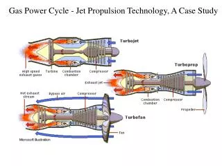
Project 2: Study of Separated Flow in a Low- Pressure Turbine*. Joshua Combs, Aerospace Engineering, Junior, University of Cincinnati Devon Riddle, Aerospace Engineering, Senior, University of Cincinnati ASSISTED BY: Michael Cline, Graduate Research Assistant

E N D
Project 2: Study of Separated Flow in a Low- Pressure Turbine* Joshua Combs, Aerospace Engineering, Junior, University of Cincinnati Devon Riddle, Aerospace Engineering, Senior, University of Cincinnati ASSISTED BY: Michael Cline, Graduate Research Assistant Dr. Kirti Ghia, Faculty Mentor *Sponsored by the National Science Foundation Grant ID No. DUE-0756921
Project Goals • Goal 1: Understand the phenomenon of flow separation on streamlined bodies. • Goal 2: Understand methodologies for analyzing and controlling flow separation.
Objectives • Objective 1: Investigate characteristics of the low-pressure turbine. • Objective 2: Explore methods of flow separation and control. • Objective 3: Disseminate findings in a technical report.
Motivation • Reduce engine weight (COST!!) i.e. use fewer blades • Increases the amount of work done by each blade • Adverse pressure gradient and low Reynolds number induces flow separation thereby decreasing low-pressure turbine (LPT) efficiency • Must CONTROL flow in LPT to reduce flow separation
Terminology Adverse Pressure Gradient (APG): Pressure increases in the flow direction John Anderson, Fundamentals of Aerodynamics, 5th • Flow Separation: Detachment from body surface Michael Cline, 2012 AY-REU Program
Terminology continued Reynolds Number (Re): Dimensionless quantity representing the ratio of inertial forces to viscous forces • Indicates whether flow is laminar or turbulent Re ≈ 10e6 Transition Region: Zone between laminar and turbulent flow Re ≈ 10e5 John Anderson, Fundamentals of Aerodynamics, 5th Boundary Layer (BL): Thin viscous region adjacent to the body
Flow Control Methods Two main categories: Active BL Suction Synthetic Jet Plasma Actuator Passive Trip Wire Vortex Generators Roughness …There are others, these are just to name a few
Passive Control Tripwire • Promotes transition from laminar BL to turbulent BL • Increases momentum to overcome APG Vortex Generator • “Re-energizes” BL • Delays flow separation (Top-Bottom): “Drag Reduction on Aerodynamic Shapes with Ground Effect”, http://www.aerospaceweb.org/question/aerodynamics/q0228.shtml
Active Control Plasma Actuators • Adds momentum through a body force. • Proven to reattach flow effectively; no fluid injection Professor Wei Shyy University of Michigan
Types of Plasma Actuators • Single Dielectric Barrier Discharge (SDBD) Plasma Actuators • Glow Discharge Actuators • Plasma Synthetic Jet Actuators
Single Dielectric Barrier Discharge Plasma Actuators • Widely utilized • Desirable features for use in air at atmospheric pressures • Active airfoil leading edge separation control • Control airfoil dynamic stall • Bluff body flow control • Boundary layer flow control • Internal and external flow applications. • Effective at high subsonic, transonic, and supersonic Mach numbers • Two electrodes separated by dielectric barrier material. • One electrode on aerodynamic surface exposed to air • Covered electrode encapsulated in dielectric material • Voltage is applied igniting the DBD • Unique: sustain large volume discharge at atmospheric pressure without arcing. Self limiting. • Flow control created through generated body force vector field mixing with the external flows momentum.
Experiment using SDBD actuators • Cylinder • Side image of the smooth flow closely attached to the cylinder. • Close up on the flow behind the cylinder. Wake is minimized. Professor Wei Shyy University of Michigan
Experiment using SDBD actuators continued • Cylinder • Side image of flow without the use of SDBD. • Close up on the flow behind the cylinder. Wake is large and out of control. Professor Wei Shyy University of Michigan
Plasma Synthetic Jet Actuator • Designed for flow control that consists of an annular electrode in quiescent and flat plate boundary layer flows. • SJA formed from the working flow of the system • Name came from: • Circular plasma region produced on the actuation generates vertical zero-net mass flux (synthetic) jet. • Actuator pulses forming a starting vortex ring. • Advects ahead of jet and secondary vortex rings near actuator surface. • Pulsing frequency is varied, creating multiple vortex rings • Vortex ring interactions • Increases peak velocity • Increases streamwise extent of the jet.
Experiment using Synthetic Jet Actuators • Investigating plasma actuators and synthetic jets to develop a plasma flow control device that is more effective. • Observed varied pulse frequencies and jet characteristics • Peak velocity • Steady operation of the actuator without pulse frequencies • Constant velocity
Experiment using Synthetic Jet Actuators continued • Both graphs show the streamwise distribution of local maximum mean axial velocity • Peak velocity pulsing at 10 Hz • Optimum time of operation is less than 24 ms • Interesting observation being that it never returns to zero velocity • Suggests optimum operational frequency closer to 10 Hz.
Computational Fluid Dynamics • Method of analyzing fluid mechanics with theoretical and experimental techniques • Utilizes algorithms and numerical methods to solve and analyze fluid flow problems • Computer carries out the calculations of time dependent interactions between the body and the fluid
…Future Work • Generate “baseline” results for the LPT • Learn how to model flow and implement into ANSYS Fluent (CFD software) • Learn to used programming languages required for CFD (i.e. C++)
19 Timeline
References • http://projei.tistory.com/47 • Huan, Junhui, Separation Control Over Low Pressure Turbine Blades Using Plasma Actuators, University of Notre Dame, 2005 • Hilbert, Brian F., Drag Reduction on Aerodynamic Shapes with Groudn Effect, Clarkston University, 2011 • Xiaoping Xu, Zhou Zhou, Ruijun Fan, JunliWang, Investigation of Active Flow Control on Aerodynamic Performance of HALE UAV Airfoil, Second International Conference on Computer Modeling and Simulation, 2010 • Shin, J., Narayanaswamy, V., Raja, L.L., Clemens, N.T., "Characterization of a Direct-Current Glow Discharge Plasma Actuator in Low-Pressure Supersonic Flow," AIAA Journal, Vol. 45, No. 7, pp. 1596-1605, 2007.