Download
1 / 25
250 likes | 259 Vues
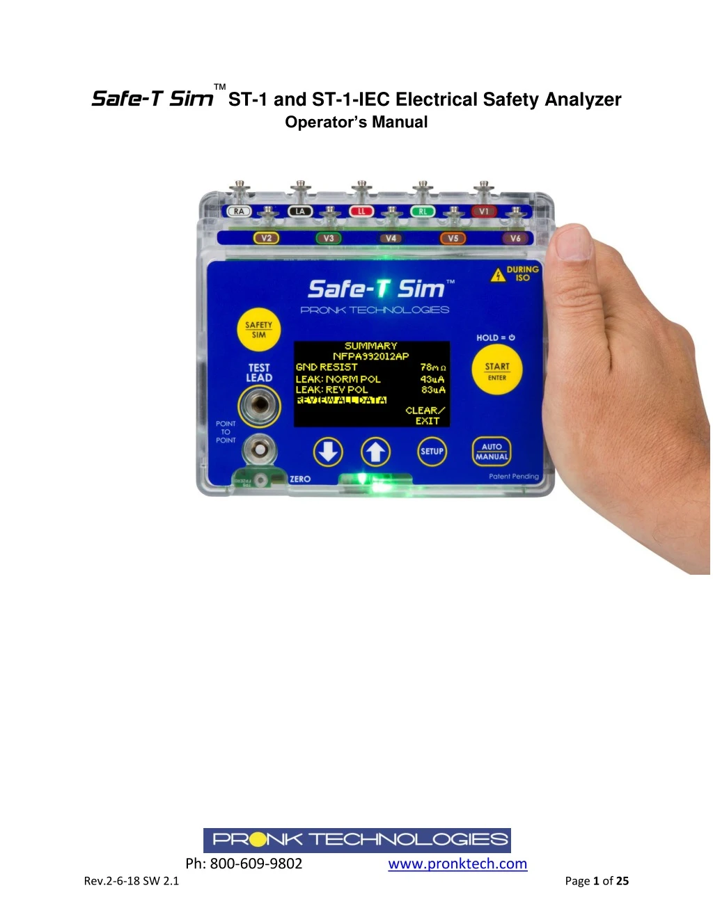
The Safe-T Sim ST-1 Electrical Safety Analyzer is quick to set up, easy to use and ready to go where you need to be. ST-1 is designed to be used in either Automatic or Manual mode. With Automatic mode, the user can customize up to 5 unique test protocols or u201cprofilesu201d enabling and disabling tests and adjusting pass/fail limits. Applied parts testing, ECG and Respiration simulations are integral in the standard product.

E N D
™ ST-1 and ST-1-IEC Electrical Safety Analyzer Operator’s Manual Ph: 800-609-9802 www.pronktech.com Rev.2-6-18 SW 2.1 Page 1 of 25
This Operators Manual relates to Analyzers with SW 2.1 or higher. This product is intended for testing purposes only and is not used in diagnostics, treatment or any other capacity where it would come in contact with a patient. The device shall only be used with the AC power cord provided or with AA Alkaline or Lithium batteries. Operate this product using only accessories provided by Pronk Technologies. If this equipment is used in a manner not specified by Pronk Technologies, the protection provided by the equipment may be impaired. Service and calibration must be performed by Pronk Technologies or a designated service organization approved by Pronk Technologies. Verify proper service and calibration by reviewing certification document returned with the device. To dispose this product, contact Pronk Technologies at support@pronktech.com. We will issue a RMA and pay for return shipment. Ph: 800-609-9802 www.pronktech.com Rev.2-6-18 SW 2.1 Page 2 of 25
Table of Contents Warnings ....................................................................................................................................................... 4 Front Panel Keys and Connections................................................................................................................ 5 Introduction .............................................................................................................................................. 5 Accessories Included ................................................................................................................................. 5 Quick Start: Automated Safety Testing ......................................................................................................... 6 Quick Start: Manual Safety Testing ............................................................................................................... 7 Quick Start: ECG/Respiration Simulation ...................................................................................................... 8 Detailed Operation: ST-1............................................................................................................................... 8 ZERO TEST LEAD: Auto and Manual Mode ............................................................................................... 8 Electrical Safety Testing: AUTO MODE ..................................................................................................... 9 Electrical Safety Testing: MANUAL MODE .............................................................................................. 10 Electrical Safety Testing: Alert Messages ................................................................................................ 10 High Current Testing ............................................................................................................................... 11 Electrical Safety Tests Available .............................................................................................................. 13 GND RESISTANCE .................................................................................................................................... 13 EARTH LEAK TESTS .................................................................................................................................. 13 CHASSIS LEAK TESTS ................................................................................................................................ 14 LEAD LEAK- GND TESTS ........................................................................................................................... 14 LEAD LEAK- ISO TESTS (MAP) .................................................................................................................. 14 Point to Point Testing (Hardwired Devices) ............................................................................................ 15 Applied Parts- Lead to Lead and Lead to Ground Testing....................................................................... 16 Simulation Mode ......................................................................................................................................... 16 Customizing Auto Profiles: Detailed ........................................................................................................... 17 Global Settings ............................................................................................................................................ 19 Audio and LED Settings ........................................................................................................................... 19 Cloning PROFILES from one ST-1 to others ............................................................................................. 19 Editing the PROFILES.CSV (or “MasterProfile.csv”) ............................................................................ 20 Clone Master File to Additional ST-1 .................................................................................................. 21 Glossary of Terms........................................................................................................................................ 22 ST-1 Troubleshooting Tips ........................................................................................................................... 23 ST-1 Limited Warranty ................................................................................................................................ 24 Standards Compliance ................................................................................................................................ 25 Ph: 800-609-9802 www.pronktech.com Rev.2-6-18 SW 2.1 Page 3 of 25
Contact Information Sales: 800-609-9802 Technical Support: 800-541-9802 FAX: 818-768-5606 Email: sales@pronktech.com Website: www.pronktech.com Warnings To avoid possible electrical shock or personal injury, follow these recommendations: 1. When Lead Leak ISO testing is being performed with the Safe-T Sim Electrical Safety Analyzer, the ECG snaps will have line voltage applied to them. This voltage is current limited but users should not touch the ECG Snaps or Device Under Test (DUT) during these tests. 2. Do not touch metal parts of the DUT during testing. The DUT is a potential shock hazard when connected to Safe-T and conducting high voltage tests. 3. ONLY use the power cord provided by Pronk Technologies to ensure 15 to 20 amp operation does not cause a temperature issue with the power cord. Ph: 800-609-9802 www.pronktech.com Rev.2-6-18 SW 2.1 Page 4 of 25
Front Panel Keys and Connections 10 ECG Patient Lead Snaps and Banana Plug jacks for Lead Leakage & ECG/Resp simulations ECG/Resp Banana Plug Jacks START/ENTER Key 1. Start Tests/Modes 2. Entering Changes 3. Power On unit (Off = Hold for 4 sec.) Safety Analyzer / Simulator Mode Key Test Lead for Resistance Testing Chassis/Enclosure Mode Key - Select Auto Test Profiles, Manual Mode or Point to Point Tests ZERO TEST LEAD and Point to Point Test Lead UP/DOWN Keys for Scrolling and soft keys Global Settings & Customizing Auto Profiles and soft key Introduction The Safe-T Sim ST-1 Electrical Safety Analyzer is quick to set up, easy to use and ready to go where you need to be. ST-1 is designed to be used in either Automatic or Manual mode. With Automatic mode, the user can customize up to 5 unique test protocols or “profiles” enabling and disabling tests and adjusting pass/fail limits. Applied parts testing, ECG and Respiration simulations are integral in the standard product. Accessories Included Carrying Case Chassis Test Lead Red- 8 foot2 AA Alkaline Batteries 10 ft. USA NEMA 5-15, 14 Gauge power cordPower Cord Secure Sleeve Fastener Operators Manual USB cable Optional: Mounting Clamp Assembly Bluetooth Interface 10 ECG Alligator Adapters Chassis Test Lead Black – 8 foot Ph: 800-609-9802 www.pronktech.com Rev.2-6-18 SW 2.1 Page 5 of 25
Quick Start: Automated Safety Testing AUTO mode can substantially speed up Safety Testing. Five factory default automated Test Profiles are preloaded onto ST-1. These profiles are editable by users on the ST-1 directly or via a PC using the USB cable provided (see Cloning Profiles section). 1. Power up ST-1 by plugging in the AC power cord provided and if needed, pressing the START key. 2. Attach Test Lead banana plug end to upper TEST LEAD jack, and Alligator clamp end of Test Lead to DUT chassis exposed metal / ground post. 3. Press AUTO/MANUAL key. 4.Highlight desired Auto Profile* and press START to select. 5. From AUTO: HOME screen, press START to begin automated test. ZERO TEST LEAD cable, if prompted.** 6.Once the test sequence is completed, the Safe-T Sim will display a SUMMARY screen showing peak values measured by category. Reviewing / Clearing Data To clear all data, exit testing and turn off power to DUT, press CLEAR/EXIT. To review all the data press START to enter REVIEW mode. In review mode, press NEXT (START) to move to next screen / category of tests or use arrow up or down within each screen of review, highlight a test and press START to retest an individual test. Press EXIT REVIEW from any review screen to return to SUMMARY screen. *Example: ST-1 NFPA99 Factory Defaults Earth Chassis N-POL N-POL-GO N-POL-GC Lead Leak: GND N-POL-GC Profile Name Ground Resistance Yes Yes Yes Yes N-POL- GO USERDEFINE1 USERDEFINE2 USERDEFINE3 NFPA992012 NFPA992012AP *NFPA99-2012 calls for testing both with the DUT on and then repeating some tests with the DUT off. Both NFPA99 profiles have been default to “Leave DUT on at end” to comply. This feature can be configured by users in SETUP. NFPA factory defaults include two profiles that comply with NFPA-99 2012 edition. Profile NFPA992012 is for testing devices with no Applied Parts (ISO tests) and NFPA992012AP is for testing devices that have Applied Parts (“AP”). These profiles can be edited, if desired. **NOTE:Zero Test Lead has factory default of once every 30 days. This value can be edited. (See section “Editing the PROFILES.CSV”) Yes Yes Yes Yes Yes Yes Yes Yes Yes Yes Yes Yes Yes Ph: 800-609-9802 www.pronktech.com Rev.2-6-18 SW 2.1 Page 6 of 25
Quick Start: Manual Safety Testing 1. Press AUTO/MANUAL key, highlight MANUAL, press START 2. MANUAL HOME: Ground Resistance and Leakage testing can be started. Scroll to desired test, press START 3. Manual Testing screen: Ground Resistance Testing shown. Press START again to accept measurement and advance Earth Leakage, or Select EXIT TESTING to return to MANUAL HOME. EXIT TESTING removes DUT power. ZERO TEST LEAD available but not required. 4. The active Leakage test is displayed on the left highlighted with an hour glass. Fault conditions can be started by pressing up or down arrow keys. Pressing START changes the active Leakage test. EXIT TESTING removes DUT power. Press START to Select next category of tests Test Selected EXIT to return to Main Menu (this will turn off DUT) Selectable Fault Conditions 5. Press EXIT TESTING once all tests required are completed. Summary results (peak values) are shown on MANUAL: HOME. To see detailed results, select REVIEW ALL DATA, then press START key to page through all results pages. Press Start Press Start NOTE: Tests can be repeated from SUMMARY screens. Highlight test using up down arrow keys, press START to begin. Press START again to end test. 6. Press CLEAR DATA from MANUAL: HOMEscreen to delete all test results. Ph: 800-609-9802 www.pronktech.com Rev.2-6-18 SW 2.1 Page 7 of 25
Quick Start: ECG/Respiration Simulation 1. Press SAFETY/SIM key 2. ECG Heart Rate is highlighted- press START to edit value (ECG HR flashes) OR 3. Down arrow to Resp Rate, press START to edit value (Resp Rate flashes) OR 4. Down arrow to AUTO SEQ, press START to change from Adult, Peds or Neo. Detailed Operation: ST-1 ZERO TEST LEAD: Auto and Manual Mode The ZERO TEST LEAD function calibrates out the resistance of the Test Lead cable. The resistance value from this function is stored in memory of the ST-1 and is automatically subtracted from resistance measurements for greater accuracy. ZERO TEST LEAD function reminders are defaulted to 30 days, but users may perform the zero function as often as they choose by scrolling to ZERO TEST LEAD from manual mode and pressing START. The Factory Default reminder can also be edited. (See section “Editing the PROFILES.CSV”) Performing ZERO TEST LEAD manually (Not Required): 1. Attach 90 degree banana end of Test Lead to upper jack. 2. Press alligator end of Test Lead into lower jack. 3. From MANUAL:HOME select GND RESISTANCE, then ZERO LEAD to perform ZERO TEST LEAD. Press Alligator to lower Jack (most accurate method) Ph: 800-609-9802 www.pronktech.com Rev.2-6-18 SW 2.1 Page 8 of 25
Electrical Safety Testing: AUTO MODE 1. Insert the DUT power cord into the DUT outlet located on the left side of the ST-1. Connect the Test Lead to the DUT chassis / enclosure ground lug or exposed metal, if available. 2. Press AUTO/MANUAL key to select desired Auto Profile. Highlight the profile, press START. 3. From the AUTO Mode Home Screen, press START to begin testing. (ZERO TEST LEAD cable, if prompted.) All of the tests that were configured “ON” will run without user interaction on the ST-1. Tests are automatically grouped and performed in the following order. 1st All Normal Polarity, 2nd All Reverse Polarity and 3rd All Open Neutral. A green or red flash will follow the completion of each test performed depending on pass/fail. NOTE:Zero Test Lead has factory default of once every 30 days. This value can be edited. (See section “Editing the PROFILES.CSV”) 4. Once all the tests that were “ON” have completed, the screen will display a SUMMARY of all results (peak values). “P” (Pass) or “F” (Fail) symbol will be posted to the right of each test category. Press START to REVIEW ALL DATA, or CLEAR/ EXIT to clear all data and start a new test (Turns off DUT Power). Measured value will be posted to the right of each test completed. Press START to advance to next page of results, EXIT REVIEW to return to SUMMARY Screen. EXIT REVIEW Press Start Press Start 5. Retesting in Auto Review Screens: From REVIEW screens for any test completed, the result can be reviewed and repeated by scrolling to that line using up or down arrow keys and pressing START key. The test will repeat and the new test result will replace the prior. This can be done for any test turned on in the Auto Profile, but not for any test that was turned off in that profile. 6. From SUMMARY screen press CLEAR/EXIT to return to AUTO: HOME screen to start a new test / new DUT. Ph: 800-609-9802 www.pronktech.com Rev.2-6-18 SW 2.1 Page 9 of 25
Electrical Safety Testing: MANUAL MODE 1. Insert the DUT power cord into the DUT outlet located on the left side of the ST-1. ZERO TEST LEAD cable, if prompted. Connect the Test Lead to the DUT chassis / enclosure ground lug or exposed metal, if available. NOTE:Zero Test Lead has factory default of once every 30 days. This value can be edited. (See section “Editing the PROFILES.CSV”) 2. From the Manual Mode Home Screen, scroll using UP or DOWN arrow keys to highlight the desired test and press START key to begin testing. 3. Leakage test being performed is displayed, as shown below, along with available fault conditions that can be selected. Press START to select next category of tests. Press START to select next category of tests Test Selected Measured Value DUT Current Draw Selectable Fault Conditions EXIT TESTING to return to Main Menu (this will turn off DUT) 4. Use UP or DOWN arrow keys to change fault conditions e.g. GND CLOSED to GND OPEN and NTRL CLOSED to NTRL OPEN. 5. Measured value is displayed along with DUT current draw. 6. Press EXIT TESTING once all tests are complete (DUT will power off). Select REVIEW ALL DATA, then press START key to page through all results. NOTE: Tests can be repeated from REVIEW screens. Highlight test by using up and down arrow keys, press START to begin. Press START again to end test. 7. Press CLEAR DATA from HOME screen to delete test results. Electrical Safety Testing: Alert Messages Electrical Safety Home Screen: When power up sequence is complete, ST-1 will display the last testing mode used (MANUAL or AUTO: Profile [X]), indications of the line voltage (polarity, ground continuity). If no fault is detected, ST-1 is ready for use. 1. If NO AC DETECTED or REVERSE POLARITY message is displayed, safety testing will be halted until the line voltage fault is no longer present. Ph: 800-609-9802 www.pronktech.com Rev.2-6-18 SW 2.1 Page 10 of 25
2. FLOATING GND: If very high resistance is detected between ST-1 and protective earth at Mains, a FLOATING GND message is displayed at the bottom of the screen. When the user presses START, the following warning message is displayed: NOTE:If you are using the ST-1 in an isolated power environment that is causing this message and are confident it will not affect accuracy of electrical safety measurements, select CONTINUE to begin testing. 3. ST-1 MEASURED <2 OHM DUT: ST-1 will perform resistance test of the DUT input and if the resistance is less than 2.1 ohms, ST-1 will post warning messages, as shown below. User should verify the medical device is functional before proceeding. High Current Testing 1. When testing devices that draw more than 15 amps, ST-1 will limit electrical safety testing to a maximum of 3 minutes continuous*. This applies anytime the ST-1 is providing AC power to the DUT including Sim and leakage testing modes, as well as, the DUT PWR AT END feature. The following timer message will be displayed in Manual Mode indicating high current draw and time left before safety testing is automatically stopped. Ph: 800-609-9802 www.pronktech.com Rev.2-6-18 SW 2.1 Page 11 of 25
High Current Testing Time Available 2. Once high current draw time limit is reached, the DUT power is removed and the following message will be displayed. ST-1 tracks the time of High Current testing and a timer will be displayed incrementing from zero seconds to show how much time is available for additional High Current tests. Users can EXIT this screen at any time, and resume high current testing for the duration of time last displayed on this screen or wait until the timer reaches the maximum of 180 seconds, then press EXIT to resume testing. High Current Testing Time Available *Safe-T Sim is designed to continuously track the amount of time that high current is being drawn by the DUT in order to ensure to limit the time to a maximum of 180 seconds. Example: If DUT current draw is 18 Amps for 120 seconds, then 1 Amp for 120 seconds, the available High Current Time after these two tests is 180 seconds. Second example: If the DUT current draw is 18 Amps for 120 seconds and then 1 Amp for 60 seconds, the available High Current Time will be 120 seconds. [(180 max. seconds avail. - 120 sec. high current used) + 60 seconds low current used = 120 seconds high current time available.] NOTE: While very unlikely, it is feasible that if many devices that draw 15+ Amps were tested sequentially and the Safe-T Sim power was removed between each device tested, the timer would not be able to manage how much time was available for High Current testing. If this were to occur and less than 3 minutes expired between High Current devices tested, the Safe-T Sim display could go blank. This is not a failure of the Safe-T Sim and only requires the user to remove the DUT and the power cord from the Safe-T Sim for 3-5 minutes and restart testing. Ph: 800-609-9802 www.pronktech.com Rev.2-6-18 SW 2.1 Page 12 of 25
Electrical Safety Tests Available Definition Provides means for zeroing out resistance from Test Lead Cable to the ST-1. Resistance is measured from the DUT Protective Earth (PE) pin to Line PE and/or from Test Lead connected to DUT enclosure to Line PE. Displays leakage current measured during different test conditions. Measurements are conducted through the DUT power cord. Chassis Leakage shows leakage current measured during different conditions. Measurements are conducted from the DUT chassis / enclosure via the Test Lead. Leakage Current measurements from the applied parts to PE where the applied parts are connected to Ground. Leakage current measurements from the applied parts to PE where the line voltage is present on the applied parts (current limited). Name ZERO TEST LEAD GND RESISTANCE Earth Leak Chassis Leak Lead Leak: GND Lead Leak: ISO GND RESISTANCE The GND RESISTANCE performs a resistance test between the Test Lead Cable and PE (Protective Earth). This measurement is performed using the Test Lead connected to exposed metal surface on the DUT. This measurement result is the resistance of the enclosure / chassis and the DUT power cord itself. The limit for Pass/Fail can be customized for each Auto Profile. Once set, the software will use this value to make decisions such as Pass/Fail for Ground Resistance Test and whether or not to beep if Beep is turned on. It will also trigger beeps / tones based on the GND AUDIO setting. EARTH LEAK TESTS When this test is started, a measurement is displayed of the leakage current in the ground wire to Protective Earth with a 1000 ohm load in series with the measurement. Tests are available in Normal and Reverse polarity, as well as, open and closed Neutral. Tests can be programmed on and off and limits are user configurable as described below. Neutral Normal Polarity (NP) Reverse Polarity (RP) LIMIT Closed On/Off On/Off 5-5000 Open On/Off On/Off 5-5000 Ph: 800-609-9802 www.pronktech.com Rev.2-6-18 SW 2.1 Page 13 of 25
CHASSIS LEAK TESTS When this test is started, a measurement is displayed of the leakage current between the DUT Chassis / enclosure via the test lead to Protective Earth with a 1000 ohm load in series with the measurement. Tests are available in Normal and Reverse polarity, Ground Closed or Open, as well as, open and closed Neutral. Tests can be programmed on and off and limits are user configurable as described below. Ground Neutral Normal Polarity (NP) Reverse Polarity (RP) LIMIT Closed Closed On/Off On/Off 5-5000 Open Closed On/Off On/Off 5-5000 Closed Open On/Off On/Off 5-5000 Open Open On/Off On/Off 5-5000 LEAD LEAK- GND TESTS When this test is started, a measurement is displayed of the leakage current between the ECG leads and Protective Earth. All 10 of the snaps on the ST-1 are electrically connected to Protective Earth with a 1000 ohm load in series. Tests are available in Normal and Reverse polarity, Ground Closed or Open, as well as, open and closed Neutral. Tests can be programmed on and off and limits are user configurable as described below. Ground Neutral Normal Polarity (NP) Reverse Polarity (RP) LIMIT Closed Closed On/Off On/Off 5-5000 Open Closed On/Off On/Off 5-5000 Closed Open On/Off On/Off 5-5000 Open Open On/Off On/Off 5-5000 LEAD LEAK- ISO TESTS (MAP) WARNING- SNAPS HOT! (High Voltage on ECG Snaps) When this test is started, a measurement is displayed of the leakage current between the ECG leads to Protective Earth. All 10 of the snaps on the ST-1 are electrically connected to mains voltage but are current limited by 121Kohms of resistance for safety. If one or more of the lead wires on the DUT has a high leakage current, they will combine in the measurement and cause a failure, depending on the user selected Pass/Fail threshold. Ph: 800-609-9802 www.pronktech.com Rev.2-6-18 SW 2.1 Page 14 of 25
Tests are available in Normal and Reverse polarity, as well as open and closed Neutral. Tests can be programmed on and off and limits are user configurable as described below. Neutral NP RP LIMIT (Normal Polarity) (Reverse Polarity) Closed On/Off On/Off 5-5000 Open On/Off On/Off 5-5000 Point to Point Testing (Hardwired Devices) Allows Measurement of resistance or leakage between two points (PTP). Black Test Lead Cable required P#: 501-9924. Press AUTO/MANUAL key, highlight POINT TO POINT TESTS, press START. 1. Point-Point Resistance Test a. First time you select PTP Resistance, it is recommended to use the ZERO LEADS function to null resistance of test leads before taking measurement. b. Connect Test Leads between the two points desired on DUT. Resistance measurement will be displayed. Press EXIT to stop test and return to prior screen. Ph: 800-609-9802 www.pronktech.com Rev.2-6-18 SW 2.1 Page 15 of 25
2. Point-Point Leakage Test a. Connect Test Leads between the two points desired on DUT. Leakage measurement will be displayed. Press EXIT to stop test and return to prior screen. Applied Parts- Lead to Lead and Lead to Ground Testing NFPA-99 2012 does not call for lead to lead or individual lead to ground testing, however, these tests can be performed using the ST-1, if required. For lead to lead testing, connect a Test Lead to the upper jack of the TEST LEADS jacks. Connect a second Test Lead to the lower jack of the TEST LEADS jacks. Connect one test lead to one ECG lead wire snap, making sure it is making electrical contact and connect the other test lead to a different ECG lead wire, making sure it is making electrical contact. Using Manual Mode, scroll to CHASSIS LEAK: N-POL GC and press START. Repeat with different combinations of lead wires, if required. If required to introduce a Ground Open condition during lead to lead testing, CHASSIS LEAK: N-POL GO mode can be used with the same connections. For individual lead to Ground testing, simply connect one individual Lead wire snap to the appropriate ECG Snap provided on the ST-1. Using Manual Mode, scroll to CHASSIS LEAK: N-POL GC and press START. Repeat with different lead wires, if required. If required to introduce a Ground Open condition during lead to Ground testing, CHASSIS LEAK: N-POL GO mode can be used with the same connections. Simulation Mode 1. Press SAFETY / SIM key to toggle to Simulation Mode. Home screen will display SIM as shown below. ECG default is 60 bpm and Respiration is 20 rpm. a. To edit ECG or Respiration rate, use UP or DOWN arrow keys to highlight rate value to be edited, then press START. Rate value will begin flashing. b. Use UP or DOWN arrow keys to edit to desired value. c. Press start again to save changes. Ph: 800-609-9802 www.pronktech.com Rev.2-6-18 SW 2.1 Page 16 of 25
2. ECG and Respiration Auto Sequence for ADULT, PEDS and NEO type patients automatically changes the values every 30 seconds, as listed in the diagrams below. Each sequence contains three rate simulations for ECG and Respiration. 3. ST-1 will retain last used Auto Seq. after it is powered off unless an Auto Test profile is run that has been configured for a different simulation Auto Sequence. Customizing Auto Profiles: Detailed Users can configure ST-1 based on their testing requirements and preferences. All tests can be configured On or Off and limits can be customized. Safe-T Sim AUTO mode Customization: 1. Press SETUP key, highlight EDIT PROFILE, then START. 2. Scroll to profile to be edited, press START. 3. General Edit Screen. Edit any value including profile Name as shown below. Press START to edit entry. When entry is flashing, use UP/DOWN arrow keys to change entry. Press start again to accept edited value. NOTE: A password may be required to edit profiles, if someone within your organization has chosen to maintain consistency of all auto profiles. If you are asked for a password during EDIT mode contact your management. EDIT: General Terminology Feature NAME Profile names can be edited and will appear on home screens when selected. GND RESIST Ground resistance test. Turn On/Off and set Pass/Fail limit. DUT ON TIME User defined delay in seconds to provide sufficient time for a device to power up completely, if required. Default is 2 seconds. DUT ON/OFF REPEAT performed to repeat all testing enabling user to change state of DUT from OFF to ON or vice versa. DUT PWR AT END Configure ON/OFF. When ON, at end of electrical safety tests performed, power at DUT outlet on the Safe-T Sim will be ON. SIM AUTO SEQ Configure for blank (off), Adult, Peds or NEO. If Adult, Peds or Neo selected in profile, that sequence will be active at the end of the Safety Testing. Definition Configure ON/OFF. When ON, will prompt user at end of electrical safety tests Ph: 800-609-9802 www.pronktech.com Rev.2-6-18 SW 2.1 Page 17 of 25
4. Press START to advance to EDIT: EARTH LEAK tests. Use UP/DOWN arrow keys to highlight value to be edited. Press START to edit value. When Limit value is flashing, use UP/DOWN arrow keys to change value. Press start again to accept edited value. Pressing EXIT on any EDIT screen to SAVE changes 1. Press START to advance to EDIT: CHASSIS LK tests. Use UP/DOWN arrow keys to highlight value to be edited. Press START to edit value. When Limit value is flashing, use UP/DOWN arrow keys to change value. Press start again to accept edited value. 4. Press START to advance to EDIT: LEAD LK GND tests. Use UP/DOWN arrow keys to highlight value to be edited. Press START to edit value. When Limit value is flashing, use UP/DOWN arrow keys to change value. Press start again to accept edited value. 5. Press START to advance to EDIT: LEAD LK ISO tests. Use UP/DOWN arrow keys to highlight value to be edited. Press START to edit value. When Limit value is flashing, use UP/DOWN arrow keys to change value. Press start again to accept edited value. 2. Once edits are complete, press EXIT, then SAVE, to save changes. NOTE: Profiles are saved even after power down / power on. Profiles can also be “cloned” using a PC and the USB cable provided. See section “Cloning PROFILES from one ST-1 to others” Ph: 800-609-9802 www.pronktech.com Rev.2-6-18 SW 2.1 Page 18 of 25
Global Settings The following features are global settings, meaning they influence both Manual and Auto modes. They are found in the SETUP page. Audio and LED Settings AUTO AUDIO: When ON, the ST-1 will beep during and after automated testing is completed where one or more tests fail user defined test limits. GND AUDIO: This feature is designed to make testing easier where an audible tone can be used to confirm a good ground connection has been established using the test lead. It can be set for ON/OFF, BEEP GND or BEEP OPEN. A. BEEP GND: Beeps when ground resistance is within limits. B. BEEP OPEN (recommended): Beeps when ground resistance is not yet within the limit defined in the Auto Profile. (See below). Name Definition EDIT PROFILE Selecting EDIT PROFILE will take users to an edit screen where any of 5 Auto Profiles can be edited for: Tests ON/OFF and Test Pass / Fail Limits. Users may also define how the ST-1 acts between and after any of the 5 automated safety tests are completed. Configure ON/OFF. When ON, the ST-1 will beep after Automated testing is completed where one or more tests fail defined test limits. The ST-1 enclosure will also flash green (pass) or red (fail) after each automated test is complete, as well as, glow red at the end of testing if one or more automated tests failed. Configure ON/OFF. BEEP GND: Beeps while ground resistance is within limits. BEEP OPEN: Beeps while ground resistance is not yet within limits. (RECOMMENDED) Selecting ABOUT will display the Software Versions and options configured on the ST-1. AUTO AUDIO GND AUDIO ABOUT Cloning PROFILES from one ST-1 to others Once Profiles are customized and saved to desired test requirements, follow the steps below to save all the test profiles to a PC and clone to other ST-1 units. Storing Master File of Auto Profiles to PC/Mac: 1. Connect the ST-1 to AC power and to PC using USB cable provided. 2. Once the ST-1 has displayed a menu, press and hold the START key for 4-5 seconds to turn it off. Ph: 800-609-9802 www.pronktech.com Rev.2-6-18 SW 2.1 Page 19 of 25
3. Next, while pressing and holding the down arrow key on the ST-1, momentarily press the START key, and then release both keys. 4. After 5-20 seconds, the ST-1 will appear as a “drive” or device on the PC within the file manager. If the new device Safe-T Sim does not appear on the File Explorer (or Finder) try unplugging the USB cable and reinserting. 5. From PC, open the volume / drive named Safe-T Sim. 6. Select the file named PROFILES.CSV, then copy and paste (or drag) that file onto your PC into a folder where it can be found later. Consider renaming the file as “MasterProfile.csv” or similar. 7. When finished, disconnect the USB Cable from both PC and the ST-1. Remove all power from the ST-1 and power up normally. Editing the PROFILES.CSV (or “MasterProfile.csv”) Often times it is easier to edit the profiles data on your computer. 1. Make a copy of a PROFILES.CSV from a ST-1 using the above steps [1-7]. 2. Using your preferred spread sheet application (i.e. Excel, Open Office Calc.) open the copied PROFILES.CSV stored on your computer. Make sure when importing the file that comma delimiters are turned on. 3. Row 1 of the file is for comments and can contain any data. The line must start with the characters: “PROFILES” to be valid and for the Safe-T Sim to accept new profiles later. “PROFILES of Safe-T Sim” 4. Row 2 is the version line and the first 29 characters of this line are shown on the ST-1 when it is booting up. Use this for naming your own custom profiles (e.g. “General Hospital Profile 7-12-2017”. “NFPA-99 2012” (factory Default) 5. Row 3 has Global Settings. Every pair of cells is used and its tag to the left specifies its meaning with ranges in parenthesis. ZeroLim = maximum resistance allowed for Test Lead Cable for Zero Test Lead function. Default is 35mOhms. Range is 15-150mOhms. ZeroDays= Frequency required to Zero Test Lead Cable. Default is 30 days. Range is 1-180 days. Password = 0000 will turn off password protection (factory default). Create password by choosing value between (0001-9999). When enabled password will be required to Auto Profile settings. ZeroLim(15-150) 25 ZeroDays(1-180) 6. Row 4 is a header for columns A through G. 7. Column C through G are the profiles. Please use the column header on row 5 and the range information on row 31 as a guide when modifying the settings. NOTE: Do NOT modify Test Categories or Fault Conditions information. 8. Cells A6 through A30 are all available electrical safety tests names. 9. Cells B6 through B30 are AC line conditions for the electrical safety tests in cells A6 through A30. 30 Password(0000-9999) Ph: 800-609-9802 www.pronktech.com Rev.2-6-18 SW 2.1 Page 20 of 25
10. Cells C6-C30, D6-30, E6-E30, F6-F30, G6-G30 are Test Limits that can be customized. 0=Test OFF, ON = values between 5-5000 for test limit. 11. Rows 33-36 are for setting additional features in the Auto Profile. See section “Customizing Auto Profiles: Detailed” for definitions. 12. When saving your changes to be loaded on a ST-1, make sure to use only DOS or ASCII character sets. Unicode or Macintosh style data will not work correctly. Only save the data as comma separated variable text format (CSV). Clone Master File to Additional ST-1 To store Master PROFILE to another ST-1, follow these steps below. 1. Repeat steps 1-5 of “Storing Master File of Auto Profiles to PC/Mac” from above to access the Safe-T Sim volume / drive. 2. Select and copy the PROFILES.CSV (or custom name it was saved as i.e. MasterProfiles.csv) located on the PC to copy to other ST-1’s using the copy/paste method. Alternatively, the “drag and drop” method can be used to copy the file onto the target ST-1. NOTE: A message may appear on the PC warning that the file exists and do you want to replace it. Select YES or OK to replace it. 3. Once copied, the Safe-T Sim volume / drive will disappear from your PC and then reappear after a short time. Once the volume has reappeared, please notice that your file has now replaced the file PROFILES.CSV and the name has not changed even if your copied file was named differently. 8. Disconnect the USB Cable from both PC and the ST-1. Remove all power from the ST-1 and power up normally. Note 2: When the ST-1 starts, please notice at the bottom of the first screen, a message stating FOUND PROFILES.CSV, then UPDATING PROFILES will be displayed if no errors are found. Finally, the profiles revision stored on row 2 of the CSV is shown. This process should not take more than 10-20 seconds. If errors are found in the new PROFILES.CSV, the message PROFILES.CSV ERROR is displayed and the previous profiles settings are restored. Errors are generally due to fields out of normal range or file corruption. Please inspect your master file if errors occur. Ph: 800-609-9802 www.pronktech.com Rev.2-6-18 SW 2.1 Page 21 of 25
Glossary of Terms Name Definition SAFETY / SIM START / ENTER Key to switch between electrical safety testing and simulation modes. Key to start individual test in manual mode or a series of tests in auto mode. Press and HOLD for 4+ seconds to turn off ST-1. Press again to turn back on. Key to configure the way ST-1 functions during testing, including beeps, flashing LED, ground resistance limit and more. Key to select either Manual mode, an Automated test sequence (Profile) or Point to Point Tests. Automated test sequences are user configurable. Automatic testing based on user defined tests. ST-1 will automatically run user defined test, advance and automatically run the next test until all tests enabled are completed. 5 auto tests (Profiles) are available. Once edited, these profiles are available every time the ST-1 is powered on. Manual testing with ST-1 requires the user to start each individual test. ST-1 will continue measurements in an individual test until the user presses START, up or down arrow keys returning ST-1 to the Manual List screen. Perform ground resistance test and perform Zero Test Lead Cable function. All electrical safety tests can be performed manually with AC line in Normal polarity. SETUP AUTO / MANUAL Auto Manual Test Ground Leakage: Norm Polarity Leakage: Rev Polarity Profile All electrical safety tests can be performed manually with AC line in Reverse polarity. Profiles are user defined automatic test sequences. Users can name each profile with a custom name. Up to 5 profiles can be programmed. Review results for most recent tests performed in Manual or Auto Mode Delete most recent test results. Connect the test lead to the top TEST LEAD jack and DUT enclosure/chassis for performing ground / chassis resistance and leakage testing. Connect test leads to both jacks to perform Point to Point Measurements. Protective Earth Ground Chassis (Enclosure) of the DUT Polarity- as it applies to Hot vs. Neutral Leakage Current between the Ground wire of the DUT power cord and Protective Earth. This message appears at interval programmed. Factory default is every 30 days. User must “ZERO TEST LEAD” by connecting Test Lead to the top TEST LEAD jack and opposite end to the lower TEST LEAD jack then press START. Over Limit Pass Fail Perform measurements between two points when DUT cannot be plugged into ST-1. Resistance and Chassis Leakage tests available. Review Summary Clear Summary TEST LEAD PE GND Chassis POL Earth Leak ZERO TEST LEAD REQ OL P F POINT to POINT TESTS Ph: 800-609-9802 www.pronktech.com Rev.2-6-18 SW 2.1 Page 22 of 25
ST-1 Troubleshooting Tips HOW TO FIX ERROR MESSAGE CAUSE WHEN CAN IT OCCUR 1.Remove the DUT from the SAFE-T. 2.Click START to return to main screen. DUT CURRENT DRAW > 20 Amps When a test is running. a ERRO R 1.Remove power from SAFE-T. 2.Wait a moment. 3.Re-connect power to SAFE-T. DUT CURRENT DRAW > 22+Amps. Circuit breaker trips to remove power from DUT. When a test is running. D U T EX C EED S 2 0 A M P S ! R EM O V E P O W ER F R O M S A F E- T . a ERRO R 3.Remove the DUT from the SAFE-T. 4.Click START. 5.Re-connect DUT after servicing. Leakage current > 5mA. When a leakage test is running. L EA K A G E EX C EED S 5 mA ! U N P L U G D U T F R O M S A F E- T . C O N T I N U E 1.Verify DUT operational and that there is no short on DUT. 2.Connect DUT to wall plug to verify functionality if needed. 3.Unit operational, reconnect to ST. If not, DUT requires service. 4.If normal for DUT to have low input resistance, select Run Test. ST-1 measured DUT resistance less than 2.1 ohms between hot and neutral. At the start of leakage test. 1.Pressing Exit will return user to prior home screen (either manual or Auto mode). 2.IF ERROR screen showed 180 sec at time of exit, that is available time to run more 15+ amp testing. DUT CURRENT DRAW exceeded 15+ Amps for more than 180 seconds (180s accumulative*) Any mode where DUT is powered by the Safe-T Sim including: Sim mode, Leakage tests, DUT on At End feature and others. a ERRO R 3.Wait for the SAFE-T to cool. 4.Click START. SAFE-T temperature measured > 65 degrees C internally. When a test is running. S A F E- T O V ER T EM P ! A L L O W S A F E- T T O C O O L . C O N T I N U E Ph: 800-609-9802 www.pronktech.com Rev.2-6-18 SW 2.1 Page 23 of 25
When starting a safety test. Two cases: 1.Isolated Environment a.Select CONTINUE. b.Continue testing as normal. 2.Non-Isolated Environment a.Select CANCEL. b.Follow user procedures for handling a wall outlet with protective earth open. 1.Click START to close message. Plug in AC power to run electrical safety tests. SAFE-T detected very high resistance on protective earth at mains. a ERRO R If AC power is pulled, but batteries remain. When a test is running. N O A C D ET EC T ED ! T ES T A B O R T ED . C O N T I N U E TEST GND detected measured resistance lower than ZERO TEST LEAD resistance by 25 milliohms or more. When TEST GND is started. ZERO TEST LEAD function required to clear this message before Ground resistance testing can resume. a ERRO R 2.Click START to dismiss the screen. Unit enters free fall. When a test is running. S U D D EN M O T I O N D ET EC T ED ! T ES T A B O R T ED . C O N T I N U E Symptom Solution Unable to resolve problem ST-1 Limited Warranty The ST-1 Electrical Safety Analyzer is warranted against defects in materials and workmanship for a period of forty eight (48) months from the date of shipment to the original purchaser. Warranty is valid only to the original buyer. Defective equipment should be returned freight prepaid to Pronk Technologies. Equipment returned with defective parts and assemblies shall be either repaired or replaced at the manufacturer’s sole discretion. This warranty is not applicable if the unit has been opened, if repair has been attempted, if the unit has been damaged due to operation outside the environmental and power specifications for the product, or due to improper handling or use. If any fault develops, notify Pronk Technologies (see Returns and Repairs, below) giving full details of the difficulty, and include the model and serial number of the device. Upon receipt of shipping instructions, forward the device prepaid and repairs will be made at the factory. The foregoing warranty is in lieu of all other warranties expressed or implied, including but not limited to any implied warranty or merchantability, fitness or adequacy for any particular purpose or use. Pronk Technologies shall be liable only for repair or replacement of the ST-1 Electrical Safety Analyzer and optional features. Pronk Technologies shall not be liable for any incidental or consequential damages. Contact Pronk Technologies Technical Support at: 800-541-9802 Ph: 800-609-9802 www.pronktech.com Rev.2-6-18 SW 2.1 Page 24 of 25
Order Cancellation and Refund Policy You may return your item within 14 days of delivery for a full refund. We are unable to exchange items (however, if you received a defective or incorrect item, we will be happy to make an exchange). Item(s) returned for refund must be in its original condition, undamaged and with no missing parts, packed in its original packaging, and include both the original receipt and an RMA number. We will notify you via e-mail or fax of your refund once we have received and processed the returned item. You can expect a refund in the same form of payment originally used for purchase within 7 to 14 business days of our receiving your return. Returns and Repairs Please call Pronk Technologies’ Service Department at 800-541-9802 to obtain a Return Merchandise Authorization (RMA) number and the shipping address. Returns should be packaged securely in the original packaging materials. The RMA number should be clearly marked on the packaging. If the return is for a new item and is a result of our error, we will make arrangements for payment of return shipping. Otherwise, items should be returned freight prepaid to Pronk Technologies. Services Calibration is recommended on an annual basis. The Pronk Safe-T Sim calibration procedure must be followed by an authorized calibration company using NIST traceable fixtures defined in the procedure to guarantee the device meets all specifications. Standards Compliance ST-1 has been designed to provide testing capabilities in accordance with NFPA-99, AAMI and IEC standards utilizing the recommendations from AAMI in Electrical Safety Manual, 2015 Edition: A Comprehensive Guide to Electrical Safety Standards for Healthcare Facilities. ST-1 provides the flexibility to customize the test limits to comply with the standards listed. Test Load Circuit Diagrams: Safe-T Sim ST-1 Safe-T Sim ST-1-IEC AAMI load circuit diagram IEC load circuit diagram Ph: 800-609-9802 www.pronktech.com Rev.2-6-18 SW 2.1 Page 25 of 25