Download
1 / 100
1.01k likes | 1.28k Vues
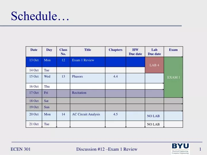
Schedule…. Examine Yourselves. 2 Cor. 13: 5 5 Examine yourselves, whether ye be in the faith; prove your own selves. Lecture 12 – Exam 1 Review. Chapters 2 - 3. Exam 1. 20 – 23 February (Tuesday – Friday) Chapters 2 and 3 18 questions 15 multiple choice (answer on bubble sheet!)

E N D
Schedule… Discussion #12 –Exam 1 Review
Examine Yourselves 2 Cor. 13: 5 5 Examine yourselves, whether ye be in the faith; prove your own selves. Discussion #12 –Exam 1 Review
Lecture 12 – Exam 1 Review Chapters 2 - 3 Discussion #12 – Exam 1 Review
Exam 1 • 20 – 23 February (Tuesday – Friday) • Chapters 2 and 3 • 18 questions • 15 multiple choice (answer on bubble sheet!) • 1 point each • 3 long answer (show your work!) • Up to 5 points each • Closed book! • One 3x5 card allowed • Calculators allowed • No time limit • Study lecture slides and homework Discussion #12 –Exam 1 Review
Exam 1 Review…Overview • Kirchoff’s current law • Kirchoff’s voltage law • Passive sign convention • Voltage/current dividers (Ohm’s Law) • Wheatstone bridge • Measuring Devices • Node voltage method • Mesh current method • Principle of superposition • Source transformation • Thévenin equivalent circuits • Norton equivalent circuits • Maximum power transfer • Dependent Sources Discussion #12 –Exam 1 Review
Exam 1 Review…KCL • What is Kirchoff’s current law? Discussion #12 –Exam 1 Review
Node a is2 is1 i2 + R2 _ Vs2 + _ Vs1 R4 i4 R3 i5 i3 R5 Exam 1 Review…KCL • What is Kirchoff’s current law? a) What is an expression for the current at Node a? Discussion #12 –Exam 1 Review
Node a is2 is1 i2 + R2 _ Vs2 + _ Vs1 R4 i4 R3 i5 i3 R5 Exam 1 Review…KCL • What is Kirchoff’s current law? a) What is an expression for the current at Node a? Discussion #12 –Exam 1 Review
Node a is2 is1 i2 + R2 _ Vs2 + _ Vs1 R4 i4 R3 i5 i3 R5 Exam 1 Review…KCL • What is Kirchoff’s current law? a) What is an expression for the current at Node a? b) what expressions for the current through R2 are valid? Discussion #12 –Exam 1 Review
Node a is2 is1 i2 + R2 _ Vs2 + _ Vs1 R4 i4 R3 i5 i3 R5 Exam 1 Review…KCL • What is Kirchoff’s current law? a) What is an expression for the current at Node a? b) what expressions for the current through R2 are valid? Discussion #12 –Exam 1 Review
Node a is2 is1 i2 + R2 _ Vs2 + _ Vs1 R4 i4 R3 i5 i3 R5 Exam 1 Review…KCL • What is Kirchoff’s current law? a) What is an expression for the current at Node a? b) what expressions for the current through R2 are valid? Discussion #12 –Exam 1 Review
Exam 1 Review…KVL • What is Kirchoff’s voltage law? Discussion #12 –Exam 1 Review
is i1 i3 i2 + R3 – + R2 – + R1 – + _ Vs Exam 1 Review…KVL • What is Kirchoff’s voltage law? • If Vs = 3V, what are the voltages across R1, R2, and R3? Discussion #12 –Exam 1 Review
is i1 i3 i2 + R3 – + R2 – + R1 – + _ Vs Exam 1 Review…KVL • What is Kirchoff’s voltage law? • If Vs = 3V, what are the voltages across R1, R2, and R3? Discussion #12 –Exam 1 Review
Exam 1 Review…Passive Sign • What is the passive sign convention? Discussion #12 –Exam 1 Review
i i a b a b _ _ + + vba vab Exam 1 Review…Passive Sign • What is the passive sign convention? • Which element dissipates power and which generates power? Discussion #12 –Exam 1 Review
i i a b a b _ _ + + vba vab Exam 1 Review…Passive Sign • What is the passive sign convention? • Which element dissipates power and which generates power? • Passive Element (load) • power dissipated = vi • power generated = -vi • Active Element (source) • power dissipated = -vi • power generated = vi Positive voltage Negative voltage Discussion #12 –Exam 1 Review
ie = 2A – 3V + B ia + 10V – E D A id =3A C – 5V + Exam 1 Review…Passive Sign • What is the passive sign convention? • Find the power dissipated by each element Discussion #12 –Exam 1 Review
ie = 2A – 3V + a B ia + 10V – E D A id =3A C – 5V + Exam 1 Review…Passive Sign • What is the passive sign convention? • Find the power dissipated by each element + va – + 10V – Loop1 NB: since load D and load E share the same nodes their voltages will be the same Discussion #12 –Exam 1 Review
Exam 1 Review…Passive Sign • What is the passive sign convention? • Find the power dissipated by each element ie = 2A – 3V + B ia = 5A + 10V – + 12V – + 10V – E D A id =3A C – 5V + Discussion #12 –Exam 1 Review
Exam 1 Review…Dividers • What is a voltage/current divider? Discussion #12 –Exam 1 Review
Exam 1 Review…Dividers • What is a voltage/current divider? Discussion #12 –Exam 1 Review
+ Vs _ Exam 1 Review…Dividers • What is a voltage/current divider? • Using a voltage divider find the voltage across R3 Vs = 3V, R1 = 10Ω, R2 = 6Ω, R3 = 8Ω – v1 + i R1 + v2 – R2 + v3 – R3 Discussion #12 –Exam 1 Review
– v1 + i + R1 Vs _ + v2 – R2 + v3 – R3 Exam 1 Review…Dividers • What is a voltage/current divider? • Using a voltage divider find the voltage across R3 Vs = 3V, R1 = 10Ω, R2 = 6Ω, R3 = 8Ω Discussion #12 –Exam 1 Review
i1 i3 i2 – R3 + – R1 + – R2 + is Exam 1 Review…Dividers • What is a voltage/current divider? • Using a current divider find i1 R1 = 10Ω, R2 = 2 Ω, R3 = 20 Ω, Is = 4A Discussion #12 –Exam 1 Review
i1 i3 i2 – R3 + – R1 + – R2 + is Exam 1 Review…Dividers • What is a voltage/current divider? • Using a current divider find i1 R1 = 10Ω, R2 = 2 Ω, R3 = 20 Ω, Is = 4A Discussion #12 –Exam 1 Review
c R1 R3 va vb a b + vs R2 Rx _ d Exam 1 Review…Wheatstone • What is the voltage across the terminals a and b of the Wheatstone bridge? Discussion #12 –Exam 1 Review
c R1 R3 va vb a b + vs R2 Rx _ d Exam 1 Review…Wheatstone • What is the voltage across the terminals a and b of the Wheatstone bridge? Discussion #12 –Exam 1 Review
Exam 1 Review…Measuring • How do measuring devices connect to circuits? Discussion #12 –Exam 1 Review
R Ω Exam 1 Review…Measuring • How do measuring devices connect to circuits? NB: the resistance of an element can only be measured when the element is disconnected from all other circuit elements Discussion #12 –Exam 1 Review
R1 A + vs _ i R2 Exam 1 Review…Measuring • How do measuring devices connect to circuits? NB: 1. the ammeter must be connected in series with the circuit element 2. the ammeter should not restrict the flow of current (i.e. cause a voltage drop) – an ideal ammeter has zero resistance Discussion #12 –Exam 1 Review
+ R2 – + v2 – V + vs _ i Exam 1 Review…Measuring • How do measuring devices connect to circuits? NB: 1. the voltmeter must be connected in parallel with the circuit element 2. the voltmeter should not draw any current away from the element – an ideal voltmeter has infinite resistance Discussion #12 –Exam 1 Review
R1 + R2 – W + vs _ i Exam 1 Review…Measuring • How do measuring devices connect to circuits? NB: 1. the wattmeter must be connected in parallel with the circuit element, but also in series with the circuit. – a wattmeter is simply the combination of a voltmeter and an ammeter Discussion #12 –Exam 1 Review
Exam 1 Review…Node Voltage • What is the node voltage method of circuit analysis? Discussion #12 –Exam 1 Review
R2 ia ib R4 R3 R1 Exam 1 Review…Node Voltage • What is the node voltage method of circuit analysis? • Find all unknown voltages ia = 1mA, ib = 2mA, R1 = 1kΩ, R2= 500Ω, R3 = 2.2kΩ, R4 = 4.7kΩ Discussion #12 –Exam 1 Review
i2 vb Node b Node a va + R2 – + ib – + R4 – + R3 – + R1 – i1 i3 i4 vc Node c Exam 1 Review…Node Voltage • What is the node voltage method of circuit analysis? • Find all unknown voltages ia = 1mA, ib = 2mA, R1 = 1kΩ, R2= 500Ω, R3 = 2.2kΩ, R4 = 4.7kΩ • Label currents and voltages (polarities “arbitrarily” chosen) • Choose Node c (vc) as the reference node (vc = 0) • Define remaining n – 1 (2) voltages • va is independent • vb is independent • Apply KCL at nodes a and b + ia – Discussion #12 –Exam 1 Review
i2 vb Node b Node a va + R2 – + ib – + R4 – + R3 – + R1 – i1 i3 i4 vc Node c Exam 1 Review…Node Voltage • What is the node voltage method of circuit analysis? • Find all unknown voltages ia = 1mA, ib = 2mA, R1 = 1kΩ, R2= 500Ω, R3 = 2.2kΩ, R4 = 4.7kΩ • Apply KCL at nodes a and b + ia – Discussion #12 –Exam 1 Review
i2 vb Node b Node a va + R2 – + ib – + R4 – + R3 – + R1 – i1 i3 i4 vc Node c Exam 1 Review…Node Voltage • What is the node voltage method of circuit analysis? • Find all unknown voltages ia = 1mA, ib = 2mA, R1 = 1kΩ, R2= 500Ω, R3 = 2.2kΩ, R4 = 4.7kΩ • Express currents in terms of voltages + ia – Discussion #12 –Exam 1 Review
i2 vb Node b Node a va + R2 – + ib – + R4 – + R3 – + R1 – i1 i3 i4 vc Node c Exam 1 Review…Node Voltage • What is the node voltage method of circuit analysis? • Find all unknown voltages ia = 1mA, ib = 2mA, R1 = 1kΩ, R2= 500Ω, R3 = 2.2kΩ, R4 = 4.7kΩ • Solve the n – 1 – m equations + ia – Discussion #12 –Exam 1 Review
Exam 1 Review…Mesh Current • What is the mesh current method of circuit analysis? Discussion #12 –Exam 1 Review
R4 ic R3 R1 R2 vs Is ia ib – + Exam 1 Review…Mesh Current • What is the mesh current method of circuit analysis? • Find the mesh currents Vs = 6V, Is = 0.5A, R1= 3Ω, R2= 8Ω, R3 = 6Ω, R4 = 4Ω Discussion #12 –Exam 1 Review
+R4– ic +R3 – + R1– + R2 – vs Is ia ib – + Exam 1 Review…Mesh Current • What is the mesh current method of circuit analysis? • Find the mesh currents Vs = 6V, Is = 0.5A, R1= 3Ω, R2= 8Ω, R3 = 6Ω, R4 = 4Ω • Mesh current directions given • Voltage polarities chosen and labeled • Identify n – m (3) mesh currents • ia is dependent (ia = is) • ia is independent • ic is independent • Apply KVL around meshes b and c Discussion #12 –Exam 1 Review
+R4– ic +R3 – + R1– + R2 – vs Is ia ib – + Exam 1 Review…Mesh Current • What is the mesh current method of circuit analysis? • Find the mesh currents Vs = 6V, Is = 0.5A, R1= 3Ω, R2= 8Ω, R3 = 6Ω, R4 = 4Ω • Apply KVL at nodes b and c Discussion #12 –Exam 1 Review
+R4– ic +R3 – + R1– + R2 – vs Is ia ib – + Exam 1 Review…Mesh Current • What is the mesh current method of circuit analysis? • Find the mesh currents Vs = 6V, Is = 0.5A, R1= 3Ω, R2= 8Ω, R3 = 6Ω, R4 = 4Ω • Express voltages in terms of currents Discussion #12 –Exam 1 Review
+R4– ic +R3 – + R1– + R2 – vs Is ia ib – + Exam 1 Review…Mesh Current • What is the mesh current method of circuit analysis? • Find the mesh currents Vs = 6V, Is = 0.5A, R1= 3Ω, R2= 8Ω, R3 = 6Ω, R4 = 4Ω • Solve the n – m equations Discussion #12 –Exam 1 Review
Exam 1 Review…Superposition • What is the superposition method of circuit analysis? Discussion #12 –Exam 1 Review
R2 R1 R3 + vR – + – vs is Exam 1 Review…Superposition • What is the superposition method of circuit analysis? • Use superposition to find vR is= 12A, vs= 12V, R1= 1Ω, R2= 0.3Ω, R3 = 0.23Ω Discussion #12 –Exam 1 Review
is Exam 1 Review…Superposition • What is the superposition method of circuit analysis? • Use superposition to find vR is= 12A, vs= 12V, R1= 1Ω, R2= 0.3Ω, R3 = 0.23Ω • Remove all sources except is • Source vs is replaced with short circuit – R2 + i2 + R1 – R3 + vR1 – i1 i3 Discussion #12 –Exam 1 Review
is Exam 1 Review…Superposition • What is the superposition method of circuit analysis? • Use superposition to find vR is= 12A, vs= 12V, R1= 1Ω, R2= 0.3Ω, R3 = 0.23Ω Node a – R2 + i2 + R1 – R3 + vR1 – i1 i3 Discussion #12 –Exam 1 Review
+ – vs Exam 1 Review…Superposition • What is the superposition method of circuit analysis? • Use superposition to find vR is= 12A, vs= 12V, R1= 1Ω, R2= 0.3Ω, R3 = 0.23Ω • Remove all sources except vs • Source is is replaced with open circuit – R2 + i2 + R1 – R3 + vR2 – i1 i3 Discussion #12 –Exam 1 Review