Download
1 / 33
330 likes | 637 Vues
Shock wave studies in solid targets. FAIR Super-FRS production targets Synergy with some targets for other accelerator facilities. Layout of Super-FRS target area. Super-FRS production targets. Slow extraction - ions extracted over few seconds Slowly rotating graphite wheel probably OK

E N D
Shock wave studies in solid targets FAIR Super-FRS production targets Synergy with some targets for other accelerator facilities
Super-FRS production targets Slow extraction - ions extracted over few seconds • Slowly rotating graphite wheel probably OK Fast extraction – the wish list! • U238 beams of up to 1012 ions/pulse • Pulse lengths 50-60 ns • Beam spot sizes σx = 1 mm, σy = 1 mm • Power densities 40 kJ/g • T=30,000C → Instantaneous evaporation of any material
Fast-extracted beams: Target options under consideration: • Increase beam spot size – obvious easy option • For low projectile Z and low intensities - use a PSI style rotating graphite wheel (as planned for slow extraction) • For highest intensities – windowless liquid metal jet
CCLRC work programme for FAIR Study of: Solid (graphite) target Liquid Li target Beam Dump Informal agreement between CCLRC and GSI: Chris Densham, Mike Fitton, Matt Rooney (CCLRC), Helmut Weickl, Klaus Sümmerer, Martin Winkler, Bernhard Franzke (GSI)
CCLRC work programme for FAIR:Solid Target • For a U238 beam, σx = 1 mm, σy = 2 mm on a graphite target: • What are the maximum positive and negative stress waves that traverse the graphite after the impact of the ion pulse? • What are the technical limits of these shock stresses? • What is the expected lifetime of a graphite target? • What U beam spot size would give a target lifetime of 1 year?
CCLRC Work Programme for FAIR: Liquid Metal target • For high intensity, high Z, highly focussed beam • Simulation of liquid lithium target to determine limiting factors of design is required. • Simulations should include • Free surfaces (predict ejection of Lithium) • Shock waves • 3D • An appropriate EOS model • Experiments similar to RIA, but with pulsed beam would be necessary for validation.
CCLRC work programme for FAIR Beam Dump • Primary beam is stopped in graphite • Secondary beam stopped in subsequent Fe layer • Calculate temperatures / shock waves in C/Fe interface and coolant pipes • Optimise design to maximise lifetime
The PSI muon production target • Rotating graphite disc • CW Proton beam • Considerable experience gained at PSI, e.g. bearings, materials • Planned to adapt design for FAIR – want c.4 g/cm2
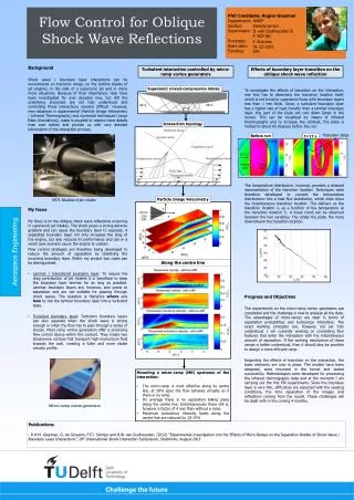
Beam axis R 2 mm LIFETIME OF THE ROTATING POLYCRYSTALLINE GRAPHITE TARGET CONES Radiation-induced anisotropic shrinkageof polycrystalline graphite causes deformation of the shape and hence leads to a radial wobble. The radial displacement amplitude R must be 2mm for the operation of the target. Measured radial displacement rates for the targets made from the graphite grades R6300P and R6400P *) *) SGL Carbon, D-53170 Bonn, Germany A new design of graphite wheel. The target cone is subdivided into 12 segments separated by gaps of 1mm at an angle of 45o to the beam direction: This allows unconstrained dimensional changes of the irradiated part of the graphite. Paul Scherrer Institut • 5232 Villigen PSI ICFA-HB2002 / G. Heidenreich
Expected radiation damage of the target The approximation formula used by NuMI target group : 0.25dpa/year MARS simulation : 0.15~0.20 dpa/year Dimension change …shrinkage by ~5mm in length in 5 years at maximum. ~75mm in radius Degradation of thermal conductivity …decreased by 97% @ 200 C70~80% @ 400 C Magnitude of the damage strongly depends on the irradiation temperature. It is better to keep the temperature of target around400 ~ 800 C 800oC 400oC Thermal conductivity (After/Before) (dpa) 1 2 3 Irradiation Effect of Graphite 800 1000 400 600 Irradiation Temperature(℃) JAERI report (1991) 2dpa -0.5% 1dpa Dimension change Toyo-Tanso Co Ltd. IG-11
T2K experiment 10-1 sin22q13 >0.006(90%) Dm132 (eV2) 10-2 CHOOZ excluded ~20 10-3 10-4 10-3 10-2 10-1 1 Long baseline neutrino oscillation experiment from Tokai toKamioka. Sensitivity on ne appearance ~1GeV nm beam (100 of K2K) Super-K: 50 kton Water Cherenkov J-PARC 0.75MW 50GeV PS Physics motivations • Discovery of nmne appearance • Precise meas. of disappearance nmnx • Discovery of CP violation (Phase2)
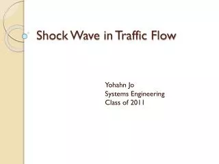
Distribution of the energy deposit in the target (w/ 1 spill) J/gK degree MARS cm T2K target conceptual design • Graphite Bar Target : r=15mm, L=900mm (2 interaction length) • Energy deposit … Total: 58kJ/spill, Max:186J/g DT 200K • Co-axial 2 layer cooling pipe. • Cooling pipe: Graphite / Ti alloy (Ti-6Al-4V), Refrigerant: Helium (Water)
Streamlines showing velocity in the helium. Calc. by John Butterworth
T2K graphite target temperature progression during first 80 seconds 80 s
Primary Beam Default acceleration cycle for 50GeV • 50 GeV (40 at T=0) • single turn fast extraction • 3.3x10¹⁴proton/pulse • 3.53 sec cycle • 750kW (~2.6MJ/pulse) • 8 (15) bunches • e=6p (7.5p)mm.mr @ 50 (40) GeV 0.7s 1.96s acceleration 0.12s injection 0.7s idling 598ns Total ~3.53s (from TDR) Idling time is to adjust total power. If beam loss, power consumption allow, this can be reduced. 4.2ms 58ns
Codes used for study of shock waves • Specialist codes eg used by Fluid Gravity Engineering Limited – Arbitrary Lagrangian-Eulerian (ALE) codes (developed for military) • Developed for dynamic e.g. impact problems • ALE not relevant? – Useful for large deformations where mesh would become highly distorted • Expensive and specialised • LS-Dyna • Uses Explicit Time Integration (ALE method is included) • suitable for dynamic e.g. Impact problems i.e. ΣF=ma • Should be similar to Fluid Gravity code (older but material models the same?) • ANSYS • Uses Implicit Time Integration • Suitable for ‘Quasi static’ problems ie ΣF≈0
Implicit vs Explicit Time Integration • Implicit Time Integration (used by ANSYS) - • Finite Element method used • Average acceleration calculated • Displacements evaluated at time t+Δt • Always stable – but small time steps needed to capture transient response • Non-linear materialscan be used to solve static problems • Can solve non-linear (transient) problems… • …but only for linear material properties • Best for static or ‘quasi’ static problems (ΣF≈0)
Implicit vs Explicit Time Integration • Explicit Time Integration (used by LS Dyna) • Central Difference method used • Accelerations (and stresses) evaluated at time t • Accelerations -> velocities -> displacements • Small time steps required to maintain stability • Can solve non-linear problems for non-linear materials • Best for dynamic problems (ΣF=ma)
Can ANSYS be used to study proton beam induced shockwaves? • Equation of state giving shockwave velocity: For tantalum c0 = 3414 m/s Cf: ANSYS implicit wave propagation velocity :
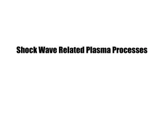
T2K graphite target shock-wave progression over 50 µs after 4.2 µs beam spill, cross-section of long target. 7 MPa (~OK?) 5 μs (end of beam spill)
2 g/cm2 graphite stress wave plots from 50 GeV protons Max Von Mises Stress: Ansys – 7MPa LS-Dyna – 8Mpa Max Longitudinal Stress: Ansys – 8.5MPa LS-Dyna – 10MPa Ansys (RAL) LS-Dyna (Sheffield)
Shock wave experiment at RAL Pulsed ohmic-heating of wires may be able to replicate pulsed proton beam induced shock. current pulse Ta or graphite wire
50kV, ~8kA PSU 50Hz At ISIS, RAL
Doing the Test The ISIS Extraction Kicker Pulsed Power Supply 8 kA Voltage waveform Time, 100 ns intervals Rise time: ~50 ns Voltage peak: ~40 kV Repetition rate up to 50 Hz. + There is a spare power supply available for use.
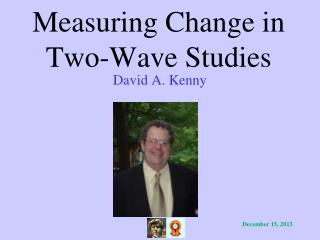
LS-Dyna calculations for shock-heating of different graphite wire radii using ISIS kicker magnet power supply G. Skoro Sheffield Uni
Temperature measurement test wire VISAR
Velocity Interferometry (VISAR) : Detector Laser Frequency ω Sample Fixed mirror Beamsplitter Velocity u(t) Etalon Length h Refractive index n Fixed mirror
Damage in tantalum wire: 1 hour x 12.5 Hz at 2200K Repeat with graphite!