Download
1 / 41
590 likes | 1.14k Vues
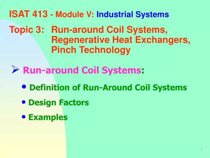
ISAT 413 - Module V: Industrial Systems. Topic 3: Run-around Coil Systems, Regenerative Heat Exchangers, Pinch Technology. Run-around Coil Systems : Definition of Run-Around Coil Systems Design Factors Examples. Run-around coil system of heat recovery.

E N D
ISAT 413 - Module V:Industrial Systems Topic 3: Run-around Coil Systems, Regenerative Heat Exchangers, Pinch Technology • Run-around Coil Systems: • Definition of Run-Around Coil Systems • Design Factors • Examples
Run-around coil system of heat recovery A run-around coil heat recovery system is the name given to a linking of two recuperative heat exchangers by a third fluid which exchanges heat with each fluid in turn as shown diagrammatically below.
Run-around coil system • A run-around coil would be used in cases where the two fluids which are required to exchange heat are too far apart to use a conventional direct recuperative heat exchanger. It is also desirable to use such an indirect system if there is a risk of cross-contamination between the two primary fluids (e.g. when a particularly corrosive fluid is involved, or when there is a risk of bacterial contamination as in a hospital). • Advantage would be free choosing of working fluid. • Disadvantage would be low effectiveness of the HX. • Typical applications are recovery of energy from the air leaving a room or building to pre-heat the air entering; and recovery of energy from a corrosive gas for water heating.
Run-around coil heat recovery between fluids with the same thermal capacity
Run-around coil heat recovery between fluids with the same thermal capacity
Example A run-around coil heat recovery system similar to that on slide 4 is used for a room in which the presence of bacteria rules out any possibility of air re-circulation or a direct recuperative heat exchanger. Air enters the room at 24oC and leaves at 20oC; the average outside air temperature during the annual period of use is 5oC. Assuming that the mass flow rate of air is 2 kg/s, mean specific heat 1.005 kJ/kg-K, that (UA)H = (UA)C = 4 kW/K, and that the specific heat of the secondary fluid is 2.5 kJ/kg-K, calculate: (i) the required mass flow rate of secondary fluid; (ii) the temperature of the air leaving the run-around coil; (iii) the percentage energy saving by using the run-around coil.
Round-around coil heat recovery between fluids of different thermal capacity
Round-around coil heat recovery between fluids of different thermal capacity
Round-around coil heat recovery between fluids of different thermal capacity
Example 5.7 (use e - NTU method to analyze run-around coil heat recovery system)
Example 5.7 A corrosive gas at a flow rate of 30 kg/s from a process at 300oC is to be used to heat 20 kg/s of water entering 10oC using a run-around oil as shown on slides 8 & 12. Calculate using the data given: (i) the mass flow rate of secondary fluid required; (ii) the effectiveness of the overall heat transfer; (iii) the exit temperature of the water; (iv) the temperatures of the secondary fluid. Data: Mean specific heat of gases, 1.2 kJ/kg-K; mean specific heat of water, 4.2 kJ/kg-K; mean specific heat of secondary fluid, 3.8 kJ/kg-K; (UA) for the gas to secondary fluid heat exchanger, 40 kW/K; (UA) for the secondary fluid to water heat exchanger, 200 kW/K.
Regenerative Heat Exchangers: • Definition of Regenerative HX • Design Factors • Examples In a regenerative heat exchanger (sometimes called a capacitance heat exchanger) the hot and cold fluids pass alternately across a matrix of material; the matrix is heated up by the hot fluid then cooled down by the cold fluid so that the process is cyclic.
Stationary Regenerative Heat Exchanger In (a) matrix B is hot and heats up the cold fluid while matrix A is heated by the hot fluid; in (b) the cold fluid is now heated by matrix A while the hot fluid re-heats matrix B; the valves are then switched over and the cycle commences again as in (a) .
Rotary Regenerator or Thermal Wheel A matrix of material is mounted on a wheel which is rotated slowly through the hot and cold fluid streams as shown above. It is known as the thermal wheel, and Ljungstrom rotary regenerator after its Danish inventor.
Example 5.8 (A rotary regenerator) A rotary regenerator is used to recover energy from a gas stream leaving a furnace at 300oC at a mass flow rate of 10 kg/s. Heat is transferred to a mass flow rate of air of 10 kg/s entering at 10oC. The wheel has a diameter 1.5 m, giving an approximate face area of 1.6 m2, and a width of 0.22 m; the matrix has a surface area to volume ratio of 3000 m2/m3 and a mass of 150 kg; the rotational speed of the wheel is 10 rev/min. The heat transfer coefficient for both fluid streams is 30 W/m2-K and the mean specific heats at constant pressure for the gas and air are 1.15 kJ/kg-K and 1.005 kJ/kg-K; the specific heat of matrix material is 0.8 kJ/kg-K. Calculate:
Example 5.8 (A rotary regenerator) (i) the effectiveness of the heat exchanger;
Example 5.8 (A rotary regenerator) (ii) the rate of heat recovery and the temperature of the air at exit;
Example 5.8 (A rotary regenerator) (iii) the air temperature at exit if the rotational speed of the wheel is increased to 20 rev/min;
Example 5.8 (A rotary regenerator) (iv) the air temperature at exit if the rotational speed of the wheel is reduced to 5 rev/min;
Gas-Fired Regenerative Burners In (a) the hot gases are fed back through the burner and through a matrix to exhaust; while in (b) air is drawn through the matrix and supplied with gas to the burner where combustion takes place; two burners are used in tandem so that continuous combustion can take place.
Magnetic Heat Pump research at Oak Ridge National Laboratory
Problem 5.9 Double Accumulator Regenerative Heat Exchanger A double accumulator as shown above is to be installed to recover energy from the air leaving a building. The air leaves the building at 20oC at a rate of 2 kg/s and the mean outside air temperature for the heating season is 5oC. Calculate the rate of the recovery, etc...
Pinch Technology Concepts: • Basic Concepts • Design Factors • Examples For many years the approach to a large network of heat exchangers was either by ‘rule of thumb’ or a systematic mathematical examination of all possible configurations to try to achieve the best layout. Another approach to network design is given the name Process Integration, or Pinch Technology.
Heat Exchanger Temperature Profiles The design of the heat exchanger is based on the minimum allowable temperature difference between the two streams being 20K. Additionalheating and cooling are required to achieve the desire temperatures.
Temperature-Heat Load representation of Heat Recovery scheme The two lines representing the streams are positioned so as to show a region of overlap which represents the action of the HX in transferring 140 KW. The minimum temperature difference occurs where the two lines are nearest together - this point is called the Pinch point.
Effect of ‘Moving’ the Cold Stream The effect of increasing the Pinch temperature difference is twofold; the amount of heat exchange between the two fluids is reduced and the external duties are increased. Note that the slope of the cold stream line is determined by the value of CC, which is 1/CC = 0.5 K/kW.
Effect of ‘Moving’ the Hot Stream • The same argument could be used for positioning the hot stream line. Thus we can say that the lines can be moved horizontally within the limits of temperature and gradient until the nearest points are separated by the minimum allowable temperature difference, that is the Pinch temperature difference. Also • To achieve the target for the external cooling duty of the hot stream, there must be no external cooling of the hot stream above the pinch. • A similar argument applies to the external heating of the cold stream below the pinch: there must be no external heating of the cold stream below the Pinch.
Stream Netwroks: • Stream Network Concepts • Design Factors • Examples Considering the design of a system of heat recovery between two (or more) hot streams and two (or more) cold streams to illustrate some fine points of Pinch Technology.
Example 6.1 (Pinch Technology) The heat flow capacities and temperatures of four streams are shown in the table below. For the purpose of definition, a hot stream is defined as one which requires cooling to reach its final temperature and a cold stream is one which requires heating to reach its final temperature. The minimum allowable temperature difference between the streams is 20 K. - 50
Composite Stream Heat Flow Capacities (Hot Stream Composite)
Composite Stream Heat Flow Capacities (Cold Stream Composite)
Combined Hot and Cold Composite Curves • From the graph the following information can be derived: • hot stream temperature at the Pinch: 120oC • cold stream temperature at the Pinch = 100oC • target external heating load = ? kW • target external cooling load = ? kW Cooling load will exceed the heating load by ? kW.
Calculations of External Cooling and Heating Loads • target external heating load = 90 kW • target external cooling load = 140 kW Cooling load will exceed the heating load by 50 kW.