Download
1 / 20
220 likes | 388 Vues
Circuits 101. Integrated Circuits (or ICs) basic packages for circuits pins determine input/output interface Categories in size SSI: 1-10 gates MSI: 10-100 gates LSI: 100-100,000 gates VLSI: over 100,000 gates. An SSI Chip. Notes on Two-Input SSI Chips.

E N D
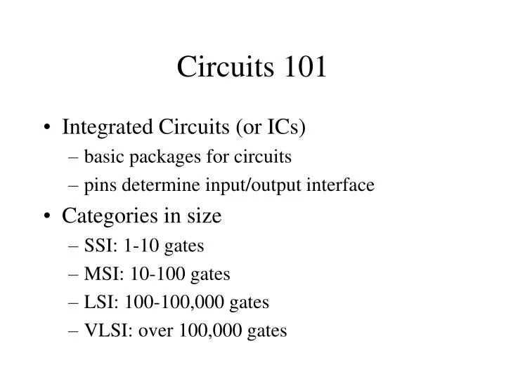
Circuits 101 • Integrated Circuits (or ICs) • basic packages for circuits • pins determine input/output interface • Categories in size • SSI: 1-10 gates • MSI: 10-100 gates • LSI: 100-100,000 gates • VLSI: over 100,000 gates
Notes on Two-Input SSI Chips • Pin 14 is where power source hooks up • Pin 7 is ground • This pin diagram is same for all two-input gate chips (AND, OR, NOR, XOR, NAND)
Circuits 102 • Combinational circuits • totally controlled by inputs • Sequential circuits • keeps a history (i.e. has a memory) • typically has a clock • controlled by inputs and what’s in memory • output at time t2 determined by inputs and memory at time t1 (memory at t1,t2 may differ)
Combinational Circuit is a Function A W B Combinational Circuit as Functional Mapping between Inputs and Outputs Z C Inputs Outputs
Sequential = Combinational + Memory + Clock Combinational Circuit as Functional Mapping between Inputs and Outputs A W B Z C Inputs Outputs Memory Clock
Typical Combinational Circuits • Multiplexers and demultiplexers • used as a selector • Encoders and decoders • used as a translator • Comparators • Shifters • Adders (half and full)
Notes on MUX • Like a traffic cop • Inputs A, B, and C indicate which output is enabled • Of the eight inputs (D0, D1, …), only one will be enabled at any given time • Thus F is set to the value of the enabled D
Notes on Decoder • Consider inputs A, B, and C a (binary) code • The outputs (could be more than one) come from a functional translation of the inputs • In this case, only one of the output lines is enabled (and it is set to 1)
Notes on Comparator • XOR determines whether or not two bits are equal • XOR produces 1 if they are different • The NOR will be 1 only if all its inputs are 0 (that is, only if all bit pairs are equal)
Notes on Shifter • An input bit is shifted left or right depending on the value of C • C = 1 means “shift right” • C = 0 means “shift left” • So, take D3 for example • if C = 1, then D3 goes to S4 and S0 = 0 • if C = 0, then D3 goes to S2 and S7 = 0
Notes on Adder • Three inputs: A and B (to be added) and Carry in from the “previous digit” • Two outputs: Sum and Carry out • Previous picture is a one-bit adder • Typically, we have an n-bit adder • many one-bit adders strung together • connected via carry bit lines
Notes on ALU • Input data: A, B, Carry in • Output data: Output bit, Carry out • Control signals • INVA, ENA, ENB, F0, F1 • collectively, these act as an ALU instruction
ALU Instructions • Gimme an A! • Gimme B • Gimme the complement of A • Gimme the complement of B • Gimme A and B • Gimme A or B • Gimme A plus B • Gimme -A plus B