Download
1 / 47
670 likes | 1.56k Vues
Lithium Batteries for Implantable Biomedical Devices – Chemistry and Applications. Presented at Indiana University March 29, 2011. Curtis F. Holmes, PhD. Greatbatch, Incorporated. Greatbatch, Incorporated.

E N D
Lithium Batteries for Implantable Biomedical Devices – Chemistry and Applications Presented at Indiana University March 29, 2011 Curtis F. Holmes, PhD. Greatbatch, Incorporated
Greatbatch, Incorporated The company was founded in 1970 by Mr. Wilson Greatbatch, an electrical engineer and the co-inventor of the cardiac pacemaker, Mr. Greatbatch believed in 1970 that the remaining problem to be solved for the pacemaker was the battery. He licensed the lithium/iodine technology, hired experienced battery scientists, and marketed the lithium/iodine battery to the pacemaker industry. By 1977, virtually all pacemakers were powered by lithium batteries. The company has grown through acquisition and market growth. Sales in 2010 were > $550 million. There are ~3000 employees at present. There are facilities in Western New York, Mexico, Minneapolis, Pennsylvania, Indiana, Switzerland, and China.
Critical Component Supplier Batteries Feedthroughs Engineered Components Capacitors EMI Filters Value Add Assembly Coated Electrodes Commercial Batteries Enclosures
What is a battery (electrochemical cell)? “Battery” means a device consisting of one or more electrically connected electrochemical cells which is designed to receive, store, and deliver electric energy. An electrochemical cell is a self-contained system consisting of an anode, cathode, and an electrolyte, plus such connections (electrical and mechanical) as may be needed to allow the cell to deliver or receive electrical energy. - Federal Government Definition
The Baghdad Battery A 2,200-year-old clay jar found near Baghdad, Iraq in 1936, has been described as the oldest known electric battery in existence. The clay jar and others like it have been attributed to the Parthian Empire — an ancient Asian culture that ruled most of the Middle East from 247 B.C. to A.D. 228. It is thought that the “battery” was used to electroplate jewelry objects with gold The nondescript earthen jar is only 5½ inches high by 3 inches across. The opening was sealed with an asphalt plug, which held in place a copper sheet, rolled into a tube. This tube was capped at the bottom with a copper disc held in place by more asphalt. A narrow iron rod was stuck through the upper asphalt plug and hung down into the center of the copper tube — not touching any part of it.
The Voltaic pile In 1799, Alessandro Volta (1745 – 1827) arranged a vertical pile of metal discs (zinc with copper or silver) and separated them from each other with paperboard discs that had been soaked in saline solution. This stack became known as the voltaic pile and was the progenitor for modern batteries. The French word for battery is “la pile.”
Cell Chemistry and Thermodynamics • Cell Voltage • Cathode materials and anode materials have different electrochemical potentials, determined by thermodynamics • The cell open circuit voltage (OCV) represents the difference of cathode and anode electrochemical potentials. The OCV of the battery is determined by the Gibbs Free Energy of the battery reaction, according the following equation: G = -nF Eº = H - T S where G is the Gibbs Free Energy, n is the number of moles transferred in the cell reaction, F is the Faraday Constant (96,500 coul/mole), and Eº is the OCV. ∆S = (nF) ∂ Eº ∂ T
Cell Chemistry and Thermodynamics • Important Battery Properties • Capacity (Ampere hours) =∫0t Idt • Energy (Watt hours) =∫0t E.Idt • Power (Watts) = E.I where I is current, E is voltage, and t is time.
Implantable Battery Applications • Pacemaker • Neurostimulator • Drug Delivery • Implantable Cardiac Defibrillator • Implantable Hearing Devices • Left Ventricular Assist Device/Totally Artificial Heart
Types of Lithium Implantable Medical Batteries • Lithium/Iodine • Lithium/CFx • Lithium/Silver Vanadium Oxide (SVO) • Lithium/Manganese Dioxide • Q Technologies High Rate – QHR Medium Rate QMR • Lithium/Hybrid (CFx and SVO Mixture) • Lithium Ion Rechargeable
Types of Lithium Implantable Medical Batteries • Two Battery Systems will be discussed in detail in this presentation – the Lithium/Iodine pacemaker battery and the Lithium/Silver Vanadium Oxide Defibrillator Battery.
What does a pacemaker cure? • We all have a pacemaker! - The heart's "natural" pacemaker is called the sinoatrial (SA) node or sinus node. It's a small mass of specialized cells in the top of the heart's right atrium (upper chamber). It generates the electrical impulses that cause the heart to beat. • The natural pacemaker may be defective (Stokes-Adams syndrome), causing the heartbeat to be too fast, too slow or irregular. The heart's electrical pathways also may be blocked. A patient with a heart beat of less than 60 BPM is said to have “bradycardia.” A heart rhythm that is too slow can cause fatigue, dizziness, lightheadedness, fainting or near-fainting spells. • Patients suffering from bradycardia need an artificial pacemaker to supply the same electrical impulses that the sinoatrial node provides in healthy people. • Over 900,000 pacemakers per year are implanted worldwide. • The first successful cardiac pacemaker, invented by Mr. Wilson Greatbatch and Dr. William Chardack, was implanted into a patient at the Veterans’ Hospital in Buffalo in 1960.
Modern Pacemaker – one battery, thousands of “transistors”
Batteries for Pacemakers • The lithium/iodine battery was developed and patented by scientists at Catalyst Research Corporation in the early 1970’s. Their invention was based on work done at the Jet Propulsion Laboratory in the late 1960’s and published in the Journal of the Electrochemical Society. Mr. Wilson Greatbatch licensed the fundamental patents from CRC and, with battery scientists Ralph Mead and Frank Rudolph, invented and patented many improvements (e. g., anode coating and the case-grounded design). • The first lithium/iodine cell was implanted in Italy in April 1972. Before that time, pacemakers were powered by zinc/mercuric oxide batteries that were short-lived, unreliable, unpredictable, and discharged hydrogen gas. • Since that time, millions of cells have been implanted. • Most pacemakers currently being implanted use lithium/iodine cells, although some advanced pacemakers are using Li/CFx, lithium hybrid cathode batteries, and QMR cells.
Batteries for Pacemakers • April 2011 will mark the 39thanniversary of the first implant of a pacemaker powered by a Li/Iodine battery. The implant occurred in Italy. • Since that time, millions of cells have been implanted. • Although several lithium-based chemical systems have seen use in pacemakers (silver chromate, cupric sulfide, thionyl chloride, manganese dioxide, titanium disulfide), the lithium/iodine battery became the only remaining pacemaker battery technology until the introduction of liquid electrolyte batteries such as Li/CFx and the “hybrid” battery (mixed CFx and silver vanadium oxide) in the last few years. It remains the most widely-used pacemaker battery today. • The battery has compiled a remarkable record of reliability and predictable performance. • It is arguably the first successful commercialization of a lithium-anode battery. • It will continue to be used for the foreseeable future.
The Lithium/Iodine battery • One could argue that, based on standard battery performance criteria, it’s not a very good battery! • It can’t start a car, run a cell phone, or even power a flashlight. • It has very high internal resistance • It doesn’t work well when it’s cold. • It doesn’t work well when it’s too hot (above 55⁰C). • Temperatures above 60⁰C will permanently damage the cell. It explodes like a bomb at 180.5ºC (the melting point of lithium). • It’s not inexpensive to manufacture. • BUT – Put it at 37⁰C and ask it to provide 10 – 50 microamperes of current, and it will do it reliably for many years.
The Lithium/Iodine Battery • It has been said that it is a very “elegant” battery system • Elegant in its simplicity • Simple cell reaction • Straightforward cell design • Elegant in its complexity • Very complicated interactions among iodine, PVP, and lithium • Performance shows a very strong dependence on cell discharge current • Elegant in its performance record • Remarkable record of reliability and usefulness for 35 years.
Lithium Anode Atomic Number: 3 Atomic Mass: 6.941 amu Melting Point: 180.54 °C Boiling Point: 1347.0 °CNumber of Protons/Electrons: 3 Number of Neutrons: 4 Classification: Alkali Metal Crystal Structure: Cubic Density @ 293 K: 0.53 g/cm3Color: silvery Ionization Potential: 5.39 eV Electrochemical Equivalent: 3.86 Ah/Gram Trivia Note: Lithium metal is one of only two materials that react with elemental nitrogen at room temperature (if humidity is present)!
Anode Coating • In the early 1970’s it was discovered by Greatbatch scientists that coating the anode with PVP dissolved in a volatile solvent greatly affected the performance of the cell. The coating was done with a camel’s-hair paint brush. The PVP was dissolved in tetrahydrofuran and painted onto the anode. The THF was dried, and the PVP remained on the anode. This improvement was patented in 1976 (patent Number 3,957,533) • The coating has a profound positive effect on the discharge characteristics of the cell. • Studies at Medtronic in the 1980’s showed that the coating led to the formation of a yellow liquid exhibiting ionic conductivity during discharge, contributing to the observed improvement in cell performance. • In 1987 a substrate coating method was developed. It is a much more efficient way of coating the anode and results in much more uniform coating weights and cell performance.
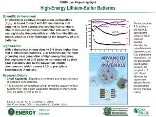
Comparison of discharge curves of uncoated and coated anode cells
Lithium Iodide Electrolyte/Separator • Ionic Salt • Density = 3.494 gr/cm3 • Lithium Ion Conductivity = 10-7 S/cm • Negligible Electronic Conductivity • Negligible Iodide ion conductivity • Self-forming, Self-healing • Structure greatly modified by coating the anode with PVP
The Iodine/Polyvinylpyridine (PVP) cathode material The Iodine/PVP material is formed by a thermal reaction between iodine and PVP. The reaction occurs above the melting point of iodine (~113⁰C). This thermal reaction is exothermic and produces a tar-like material that melts slightly below the melting point of iodine. At the 30/1 weight ratio used at Greatbatch, the material is mostly elemental iodine at unit thermodynamic activity, with a small amount of the reaction product of iodine with PVP:
Phase Diagram of the Iodine/PVP Material – dotted line is 37° C As the cell is discharged, the cathode material transitions from region 6 through region 5, and finally to region 4. Region 6 is a 2-phase system containing the eutectic melt and pure iodine. Region 5 is a single phase liquid material. Region 4 is a two-phase system wherein the one-to-one iodine/monomer unit adduct phase coexists with the melt.
Conductivity of the Iodine/PVP cathode material The conductivity of the iodine/PVP material has been shown to be electronic in nature. Electron Paramagnetic Resonance spectroscopy of the cathode material shows a single narrow signal with a g value of 2.002. This indicates that there exist free (unpaired) electrons in the material. The conductivity is a function of the ratio of iodine to PVP in the material, as shown in the next slide.
ThermodynamicCharacteristics of the Lithium/Iodine Reaction (300º K) Li + ½ I2 →LiI ∆G = ∆H - T∆S From JANAF Thermochemical Tables: ∆G = -64.451 kcal/mole ∆H = -64.551 kcal/mole T∆S = -0.101 kcal/mole ∆G = ∆H - T∆S = -nF Eº Eº = 2.8 volts ∆S = (nF) ∂ Eº ∂ T
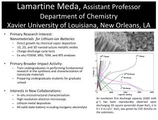
Discharge curves of a typical Li/Iodine battery at various constant resistive loads
What does an implantable defibrillator/cardioverter (ICD) cure? • Ventricular tachycardia - a potentially lethal disruption of normal heartbeat that may cause the heart to become unable to pump adequate blood through the body. The heart rate may be 160 to 240 (normal is 60 to 100 beats per minute). Uncontrolled, it can lead to ventricular fibrillation. • Ventricular fibrillation - a condition in which the heart's electrical activity becomes totally disordered. When this happens, the heart's lower (pumping) chambers contract in a rapid, unsynchronized way. (The ventricles "flutter" rather than beat.) The heart pumps little or no blood. The outcome of this condition, absent appropriate therapy, is both obvious and grim.
History of the ICD • The ICD was invented by Dr. Michel Mirowski at the Johns Hopkins University in 1979. • The first ICD’s were simple “shock boxes” that detected VF and provided the high-energy shock directly to the heart to stop the VF and restore normal sinus rhythm. They were also big – around 210 cm3. • These devices used a patch electrode that was sutured onto the heart. This meant that a thoracotomy (cracking the chest) had to be performed, and about 5% of the patients died from this major surgery. Today a transvenous lead is used, greatly reducing the trauma and the time required for the implantation. • A technique called “tiered therapy” was developed in the late 1980’s. This technique detected tachycardia and attempted to pace the patient back to normal rhythm with lower-energy pacing. It provided the high-energy shock only if it failed to restore normal rhythm by pacing. Today almost all ICD’s provide tiered therapy. The smallest ICD today is under 30 cm3.
ICD - 1989 This unit was larger than 120 cm3. It required a patch electrode that had to be sutured directly to the heart, a very traumatic and difficult surgical procedure.
ICD – 2010 The Ovatio ICD is produced by Sorin Group, a European company with locations in France and Italy. With a volume of 29 cm3, it is the smallest ICD currently on the market. The unit is connected to the heart with a transvenous lead, greatly reducing the trauma of implant surgery.
Batteries for Implantable Cardiac Defibrillators – The lithium/silver vanadium oxide battery • Scientists at Greatbatch, Inc. developed the lithium/silver vanadium oxide (Li/SVO) battery system in 1982. It was adapted for use in the implantable defibrillator a few years later. • In 1987 the first ICD powered by Li/SVO was implanted in Sydney, Australia. • Li/SVO has become the technology standard and most ICDs use the system. • SVO has the ability to deliver high power • It has high volumetric energy density
Silver Vanadium Oxide (SVO) • Silver Vanadium oxide (Ag2V4O11) belongs to a class of chemical compounds of somewhat indeterminate stoichiometry called “Vanadium Oxide Bronzes.” • They were first synthesized and studied by Casalot, Pouchard, and coworkers at the Centre national de la recherche scientifique in France. They were interested in the compound’s rather interesting magnetic properties. • SVO can be synthesized via several different reactions. The reaction used at our company is the thermal decomposition of Vanadium Pentoxide and Silver Nitrate: 2V2O5 + 2AgNO3→Ag2V4O11 + 2NO2 + 1/2O2 • The compound exists in several phases depending on the conditions of synthesis.
Li/SVO Battery Characteristics • Cell Reaction:Ag2V4O11 + 7 Li →Li7Ag2V4O11 • High Voltage: 3.2V • High Capacity: 1.37 Ah/cm3 • High Power: 20-30 mA/cm2 • DOD Indication: Staged Disch. Profile • Long Shelf Life: Self Disch.<2%/Year • Safety and Reliability: Extensively Tested • Issues Studied: Rdc Growth/V-Delay
“Q” Technology – a brief introduction • A new cell system has been developed that provides high energy density, high power and high stability • A suitable battery technology for next generation ICDs • Proven technology with patent protection and with 5 years real time cell test data • Flexible and scaleable cell design to meet the market needs • Mechanistically based performance Model developed to predict battery performance under various applications
Q Technology – Combining the Carbon Monofluoride and SVO Chemistries
Summary • Over five million people have been implanted with battery-powered devices. • Devices treat heart problems, pain, epilepsy, chronic illnesses, hearing loss, and other human illnesses. • These devices are powered by lithium batteries, which offer high energy density, reliability, and longevity. • Significant improvements in battery performance, electronic circuitry, and electrodes have permitted newer, smaller devices that perform a wide variety of functions.