Download
1 / 21
210 likes | 402 Vues
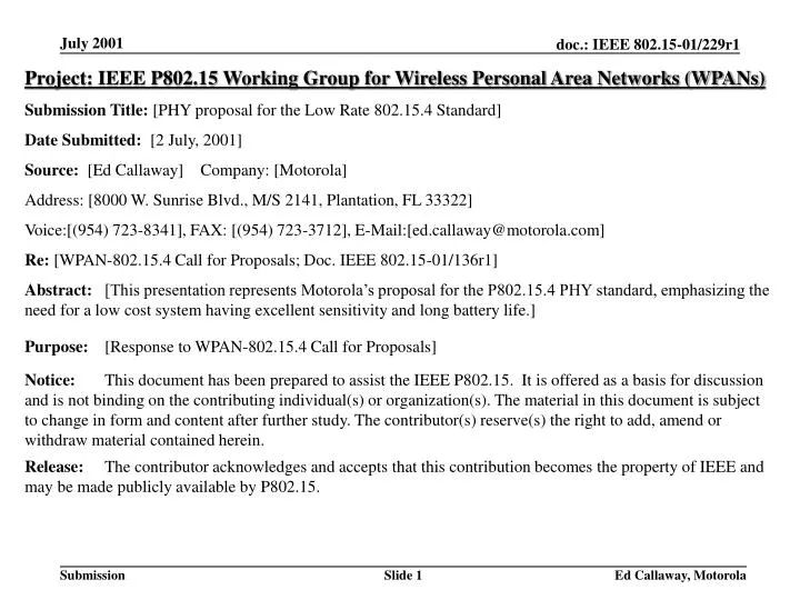
Project: IEEE P802.15 Working Group for Wireless Personal Area Networks (WPANs) Submission Title: [PHY proposal for the Low Rate 802.15.4 Standard] Date Submitted: [2 July, 2001] Source: [Ed Callaway] Company: [Motorola] Address: [8000 W. Sunrise Blvd., M/S 2141, Plantation, FL 33322]

E N D
Project: IEEE P802.15 Working Group for Wireless Personal Area Networks (WPANs) Submission Title: [PHY proposal for the Low Rate 802.15.4 Standard] Date Submitted: [2 July, 2001] Source: [Ed Callaway] Company: [Motorola] Address: [8000 W. Sunrise Blvd., M/S 2141, Plantation, FL 33322] Voice:[(954) 723-8341], FAX: [(954) 723-3712], E-Mail:[ed.callaway@motorola.com] Re: [WPAN-802.15.4 Call for Proposals; Doc. IEEE 802.15-01/136r1] Abstract: [This presentation represents Motorola’s proposal for the P802.15.4 PHY standard, emphasizing the need for a low cost system having excellent sensitivity and long battery life.] Purpose: [Response to WPAN-802.15.4 Call for Proposals] Notice: This document has been prepared to assist the IEEE P802.15. It is offered as a basis for discussion and is not binding on the contributing individual(s) or organization(s). The material in this document is subject to change in form and content after further study. The contributor(s) reserve(s) the right to add, amend or withdraw material contained herein. Release: The contributor acknowledges and accepts that this contribution becomes the property of IEEE and may be made publicly available by P802.15. Ed Callaway, Motorola
PHY Proposal for the Low Rate 802.15.4 Standard Ed Callaway, Member of the Technical Staff Motorola Labs Phone: +1-954-723-8341 Fax: +1-954-723-3712 ed.callaway@motorola.com Ed Callaway, Motorola
Features • Modified from r0 to: • Enable 250 kb/s operation • Enable easy conversion to low data rate operation • Low chip rate (1 MHz) for low power operation • O-QPSK, for constant envelope modulation • Simple, low-cost PA • 4- to 6-dB sensitivity advantage over conventional FM-DSSS approaches • Greater range for a given output power • 10 MHz channel separation • Eases channel filter requirements to lower die size & cost • Can be used for location determination Ed Callaway, Motorola
Channelization • 2.4 GHz band; 8 channels; 10 MHz channel separation f = 2405 + 10k MHz, k = 0, 1, … 7 • Fixed channelization chosen by dedicated device at network initiation • 8 channels allow for 8 simultaneous operating WPANs • 10 MHz channel spacing sufficient for location determination using DSSS TDOA methods Ed Callaway, Motorola
Spreading and Modulation • 1 Mc/s chip rate, 31.25 kS/s (32-chip pn sequences) • Offset-QPSK, with half-sine shaping • Augmented pn sequences: CP = 45 (I), CP = 75 (Q) • 8-symbol preamble used on both I & Q , augmented CP = 67 (scanning node must correlate only one PN sequence) • Differential Code Position Modulation (D-CPM) used on both I & Q. • The pn sequence on each channel is (independently) cyclically shifted to one of 16 Gray-coded positions. • Information is transmitted on each channel as the difference in chip 0 positions from one symbol to the next. • Resulting bit rate is 250 kb/s Ed Callaway, Motorola
Differential Code Position Modulation • Easily converted to low data rate of 31.25 kb/s • set I = Q, transmit 1 b/S Preamble Symbol 0010 Symbol 0000 c0 … ca+1 … c31 c0 cb+1 … c30 ca cb c31 … ca-1 I Preamble Symbol 0011 Symbol 0001 cm cn cm+1 c30 … cn-1 c0 … c31 cn+1 … c31 c0 … Q Ed Callaway, Motorola
BER BER Curve 4 dB @ 10-3 4.5 dB @ 10-4 Ed Callaway, Motorola
Orthogonal Signaling=Improved Sensitivity K = 4, 6.5 dB K = 1, 11 dB K = 4, 7.5 dB K = 4, 12.5 dB Source: Bernard Sklar, Digital Communications. Englewood Cliffs, New Jersey: Prentice-Hall, 1988, p. 179. Ed Callaway, Motorola
Receiver Implementation Options • Conventional DSSS decoding • 8 dB Eb/N0 (-98 dBm with NF = 15 dB) @ 10-4 BER, 250 kb/s • ~3 kHz (1.2 ppm) tolerable frequency offset • Excellent sensitivity; AFC needed • Differential chip decoding • 14 dB Eb/N0 (-92 dBm with NF = 15 dB) @ 10-4 BER, 250 kb/s • ~100 kHz (>40 ppm) tolerable frequency offset • Sensitivity similar to conventional DSSS; very inexpensive reference can be used Ed Callaway, Motorola
2.4 GHz DSSS Transmitter Size 2.5 x 2.5 mm die 0.18 um standard digital CMOS 1 kbit data register 1023 chip SS generator RF synthesizer & loop filter 1 mW PA 80% empty space Ed Callaway, Motorola
2.4 GHz DSSS Receiver Size • Benchmark: • 6 bit x 508 chip complex correlator, plus timing & control circuits, 0.18 um • Total active area = 4 mm2, at 60% utilization; 80k gates • Our proposal: • 4 bit x 128 chip complex correlator (for preamble) • 2, 4 x 32 chip data correlators • Timing recovery & control • Total 26k gates; 1.4 mm2, even at 60% utilization; 1k data register an additional 7k gates (0.35 mm2) • Total Tx/Rx digital: • 40k gates, 2 mm2 Ed Callaway, Motorola
Analog: PLL/frequency generation Down conversion Tx PA IF gain IF filtering: 2 poles @ 5 MHz ADC analog portion Analog total: 0.6 mm2 Digital: ADC digital portion Filtering Digital modem total: 20k gates, 1 mm2 RF Modem Ed Callaway, Motorola
Size Summary • DSSS signal recovery 2.0 mm2 • Analog 0.6 • ADC & Digital filtering 1.0 Active area total: 3.6 mm2 Ed Callaway, Motorola
Transceiver Specifications • BER~ 1E-4 PER< 2% (Assuming 12 bytes overhead + 10 bytes payload data = 176 bits/packet) • Sensitivity ~ -92 dBm using differential decoding (-98 dBm using conventional DSSS decoding) • Selectivity ~ -45 dBm adjacent channel (10 MHz offset) • Signal acquisition using DSSS preamble (8 symbols) with correlator (4-5 symbols needed to sync using AGC) Ed Callaway, Motorola
System Considerations • Multipath • 10m range (indoors) implies worst case path length = 2x10m = 60nS. Proposed system can tolerate a delay spread > 100 ns, so there should be no problem in most applications • InterferenceandJamming resistance -- Implementation dependent, can be designed to tolerate: • +20 dBm 802.11b 10m away • 0 dBm 802.15.1 1m away • Microwave ovens in quiet half-cycle • Intermodulation resistance – -20 dBm IIP3 required • Coexistence and throughput with co-located systems (multiple access) • Low duty cycle systems, interference should be low Ed Callaway, Motorola
Power / Range Power: • Duty cycle = 0.1% • Transceiver active mode = 10 mW • Transceiver sleep mode = 20 uW • Average power drain is 0.001*10 mW + 0.999 *20uW = 30 uW • If this node is supplied by a 750 mAh AAA battery, linearly regulated to 1 V, it has a battery life of 2.8 years(25,000 h). Range (250 kb/s): • Range outdoors, LOS > 100m • Range indoors= 10m • Also based on –92 dBm Rx sensitivity Ed Callaway, Motorola
Scalability • Power consumption greatly reduced in sleep mode (20 uW vs. 10 mW) • Data rate may be adjusted from 1-8 bits/symbol (31.25 – 250 kb/s); lower with additional coding • Functionalityof nodes varies with role, topology (Designated Device, Designated MD, Distributed MD) • Costper device varies according to functionality of a given node • Network size is scalable due to ad hoc nature of the network and large number of possible clusters Ed Callaway, Motorola
Bottom Line • Cost estimate is $2 for quantity of 10M (Includes everything from antenna port to bits) • Implementation size (active area) • In 0.18 um, it is 3.6 mm2 (Total active area = RF/analog + Baseband) • Technical feasibility & Manufacturability • MD demonstration and network simulations available • Matlab simulations of Code Position Modulation concept • At present, developing single chip solution • Samples available Q1 2002 Ed Callaway, Motorola
General Solution Criteria Ed Callaway, Motorola
General Solution Criteria Ed Callaway, Motorola
PHY Protocol Criteria Ed Callaway, Motorola