Download
1 / 19
210 likes | 230 Vues
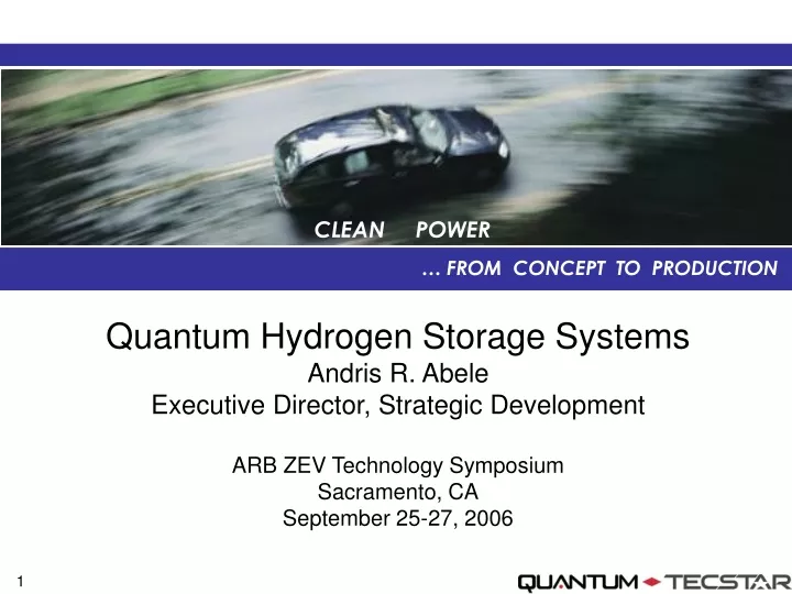
CLEAN POWER. … FROM CONCEPT TO PRODUCTION. Quantum Hydrogen Storage Systems Andris R. Abele Executive Director, Strategic Development ARB ZEV Technology Symposium Sacramento, CA September 25-27, 2006. Hydrogen Storage – It’s More Than a Tank. Contain Control Regulate Monitor.

E N D
CLEAN POWER … FROM CONCEPT TO PRODUCTION Quantum Hydrogen Storage SystemsAndris R. AbeleExecutive Director, Strategic DevelopmentARB ZEV Technology SymposiumSacramento, CASeptember 25-27, 2006
Hydrogen Storage – It’s More Than a Tank Contain Control Regulate Monitor Distribute Meter Refill Survive Hydrogen storage systems on H2 vehicles must:
Integrated Fuel Storage Systems Containment Vessel THERMAL MANAGEMENT SYSTEMS FUEL STORAGE SYSTEMS PRESSURE REGULATORS VALVES & SOLENOIDS SUPPORT STRUCTURE / BRACKETRY PRD’s, TEMP. & PRESSURE SENSORS FUEL LINES / TUBING ELECTRONICS
Quantum TriShieldTM Storage Tank Protection Layer (damage resistant) Foam Dome (impact protection) Carbon Composite Shell (structural) High Molecular Weight Polymer Liner (gas barrier) In-Tank Gas Temperature Sensor Gas Outlet Solenoid In-Tank Regulator Pressure Sensor (not visible here) Pressure Relief Device (thermal)
Tank Validation Hydrostatic Burst Extreme Temperature Cycle Ambient Cycle Acid Environment Bonfire Gunfire Penetration Flaw Tolerance Accelerated Stress Drop Test Permeation Hydrogen Cycle Softening Temperature Tensile Properties Resin Shear Boss End Material Validation Tests
Validation Testing Gunfire Testing Hydrogen Cycling Environmental Testing Burst Testing Bonfire Testing
OEM Production Level Integration Storage Injection / Metering Fuel Lines
70 MPa Hydrogen Fuel Storage System Foam Domes (Handling Safety Feature) 70 MPa Composite Tanks In Tank Regulator with Solenoid Pressure Sensors Vent Line Ports Stone Shield Vehicle Electrical Interface Connector Thermally Activated PRD Fill Line Check Valve Defueling Port (optional) Refueling Port Pressure Sensors Vehicle Interface Bracket
General Motors HydroGen3 70 MPa Hydrogen Storage Engineering
Suzuki WagonR 70 MPa Hydrogen Storage Systems
General Motors Hy-Wire 35 MPa Hydrogen Storage Systems
GM Sequel 70 MPa Hydrogen Storage Systems
DOE Storage Targets * Single 160L 70 MPa tank, 500k production volume, optimized carbon, health monitored storage system.
Compressed Hydrogen Storage System Costs Approximately 65% of System Costs are Carbon Fiber Manufacturing = 3% Components = 13% Pressure Regulator Valves Sensors (T, p) Coupling Fittings PRD Vessel = 84% Carbon Fiber Liner Material Epoxy Resin Pipes Components
Achieving DOE Targets with Advanced Manufacturing • Path for Compressed Hydrogen Technology - • Storage Centric Vehicle Design • Single Longitudinal 160L 70MPa Storage Module • On Tank Automatic Valve • External Low Cost Pressure Regulation Components • Health Monitored Tank (1.8 SP Burst Ratio) • Integrated Filament Winding w/ Fiber Placement • Revision of Codes & Standards enabling Fiber Placement • Chilled Hydrogen Supply for Fast Fill
Achieving DOE Targets with Advanced Manufacturing Estimated Performance - Usable Specific Energy (kW hr / kg) > 2.0 Usable Energy Density (kW hr / L) 0.9 Cost ($ / kW hr) < $10 Cycle Life (Cycles, 1/4 tank to full) 15,000 Refueling Rate (kg H2 / min) > 2.0
In Summary • 35 MPa and 70 MPa storage systems in use on H2 vehicles today • Extensive testing and validation completed • In use experience growing • Compressed H2 storage vessels are “the strongest part” of the vehicle • Refueling infrastructure being implemented to support compressed H2 systems • Challenges remain • Cost • Packaging on vehicles (range)
QTWW.COMNasdaq: QTWW CLEAN POWER … FROM CONCEPT TO PRODUCTION