Download
1 / 9
100 likes | 245 Vues
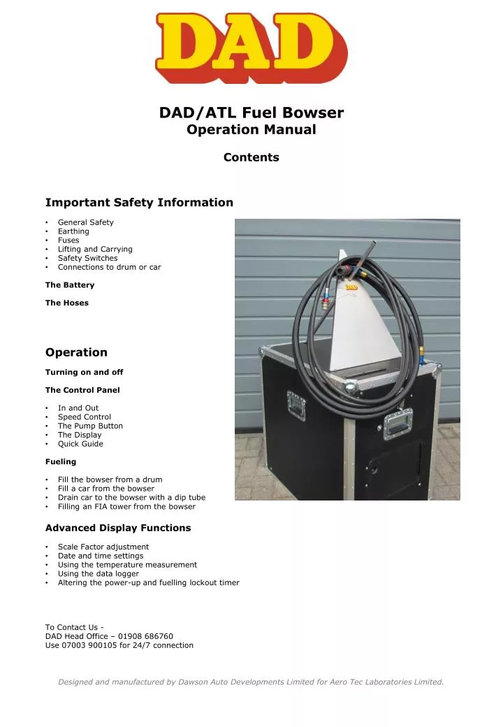
DAD/ATL F uel Bowser Operation Manual Contents. Important Safety Information General Safety Earthing Fuses Lifting and Carrying Safety Switches Connections to drum or car The Battery The Hoses Operation Turning on and off The Control Panel In and Out Speed Control

E N D
DAD/ATL Fuel Bowser Operation Manual Contents • Important Safety Information • General Safety • Earthing • Fuses • Lifting and Carrying • Safety Switches • Connections to drum or car • The Battery • The Hoses • Operation • Turning on and off • The Control Panel • In and Out • Speed Control • The Pump Button • The Display • Quick Guide • Fueling • Fill the bowser from a drum • Fill a car from the bowser • Drain car to the bowser with a dip tube • Filling an FIA tower from the bowser • Advanced Display Functions • Scale Factor adjustment • Date and time settings • Using the temperature measurement • Using the data logger • Altering the power-up and fuelling lockout timer • To Contact Us - • DAD Head Office – 01908 686760 • Use 07003 900105 for 24/7 connection Designed and manufactured by Dawson Auto Developments Limited for Aero Tec Laboratories Limited.
Important Safety Information • General Safety • Sealed Unit - If you can smell fuel there is something wrong, STOP and investigate. • The unit is hermetically sealed – this ensures that no vapour is emitted during normal use. Fuel vapour should only be detected when adrum is opened. • The bowser is designed to function safely in most environments, although general safety in respect of all inflammables should be observed. In theory it can work in a vapour atmosphere without igniting the vapour • Earthing • Electrical discharge due to static may cause sparks, given the bowser and car /drum can be at different charge levels. We suggest the use of electrically conductive hoses with a high resistance – usually 1KΩ per meter. These balance the potentials very quickly and without a spark • The FIA and ACO suggest that both car and bowser should be earthed. If an earth wire is needed it should be connected to one of the four chassis mounting bolts or manifold mounting bolts and then to an exhaust pipe on the race car. On the advice of UK MSA scrutineers, we are now supplying an earth lead with all bowsers • Lifting and Carrying • The four carry handles are placed so that the bowser unit is easy to lift and carry. There are, however, health and safety considerations. When full to capacity it can weigh 200kg • The underside of the chassis is flat which allows for forklift transfers • Safety Switches • There are three safety switches inside the unit that can stop the bowser pump from operating. • There is a float switch in the top plate that cuts the motor when the tank is full. • There is a pressure switch set at 0.65 bar on the pump outlet to stop the pump pressure being more than that (there is a bypass in the pump that opens at 1 bar but we would prefer to never see that open). • There is a pressure switch in the hose manifold set at 0.2 bar. This is to stop bladder type tanks damaging their housings. More than 0.2 bar against the underside of a saloon car floor will severely damage the floor due to the area over which the pressure is being applied. • Connections to drum or car • We strongly recommend that you always fit the vapour line to the car or drum before connecting the fuel line. This allows tank pressures to equalise before fuel is transferred • There is a breather on the bowser tank with a blow off of 0.05bar and an into tank pressure of 0.005bar. In theory this mirrors that of a car tank • Warning. Drums left in the sun after a wand has been fitted can pressurise. We strongly recommend you fit the vapour line first and let the pressures balance • Fuses • There are two fuses in the unit. • A 25 amp automotive type fuse (10A is enough) in a splash proof cover, between the Anderson Plug and the motor control unit, which is behind the battery. • A 4 amp glass fuse in the receptacle between the LEDs on the control box. Designed and manufactured by Dawson Auto Developments Limited for Aero Tec Laboratories Limited.
The Battery We recommend that the battery should be removed before transportation To access the battery, open the door on the front, put a finger in the hole and push the catch to the right. (see right) The battery is connected to the bowser with an Anderson plug, pull the top half upwards to disconnect and push it into the other half to connect Please ensure that the battery is fully charged before operating the bowser. A fully charged battery lasts for over four hours, depending upon how fast the fuel is pumped and at what pressure The bottom LED on the right side of the display flashes when the battery is close to flat. PUSH RIGHT Flashes when battery needs charging Charge the battery at 14.7 volts at up to 6 amps – at this rate it will take approximately 4 hours to fully charge the battery. A fully charged battery will have 13.8 volts at the terminals. The Hoses The standard bowser is supplied with two 7/8” UNF port plugs fitted to the standard manifold. The outer port is for fuel in and out, the inner port is for vapour. The hose adaptors should have O rings fitted to ensure a good seal to the manifold. We suggest these adaptors are removed for transportation. O Rings fitted to hose adaptors The choice of hose size is a team choice. We have found that -10 hose will not cause a flow restriction. The end fittings are usually the cause of such restrictions. The vapour return can be as small as a -6 hose without restricting the flow. However problems may arise with a -6 hose, where a car is regularly filled to the point that fuel tries to return to the bowser down the vapour line. The tank pressure will rise and possibly cause damage, see the notes regarding the low pressure switch. We can supply manifolds with M24 outlets as needed by some teams. There is also a Staubli manifold available that has the connectors recessed such that the hoses can be removed very easily and the connectors are recessed below the top face. Designed and manufactured by Dawson Auto Developments Limited for Aero Tec Laboratories Limited.
Operation Open the control box cover. Turning on and off Twist the left-hand knob in a clockwise direction, it will latch and the boot procedure will begin on the display. Push the knob down or close the lid to turn the control box off (see right). Shut down knob The Control Panel In and Out The toggle switch to the right of the display swaps the unit from ‘Into Bowser’ to ‘Into Car’. It takes 3 seconds for the unit to change over. When ready the green LED is displayed. If the bowser is full the ‘Into Bowser’ LED is turned off. Speed Control The pump speed control is located on the left of the display. Its usual working range is from 10 o’clock to 3 o’clock, 10 being a slow and efficient pump, 12 being plenty for most applications and 3 being fast for bowser or tower filling The Pump Button Pressing the pump button sets the pump control working. It takes 3 seconds to ramp up to the required speed. This extends battery life. Safety Feature. The pump only works when the button is pressed. If the button is released momentarily and then pressed again the ramp up time will be less but pumping will continue. The Display The main control panel functions are explained in the quick start guide – see below To Car Speed Control The Pump Button Designed and manufactured by Dawson Auto Developments Limited for Aero Tec Laboratories Limited.
Quick Start Guide Operating the DAD bowser weight display During the boot-up routine the display unit will scroll and show ‘Loc.Out’ until the process is complete. The display will settle on the net value of the last car used. Quick Start Guide Operating the DAD/ATL bowser weight display unit Reset display to zero Car ID Display Brightness Designed and manufactured by Dawson Auto Developments Limited for Aero Tec Laboratories Limited.
Operating the ATL-DAD bowser weight display continued… When the display boots up it shows the NET amount in Kilos. (See image right) Pressing the GROSS button will show how much is in the bowser. We suggest the last kilo is ignored. Even at a small angle fuel is trapped in a corner. The fuel display refers to mass in kilos not volume in litres It is possible to zero the display at any time when in the NET mode by pressing the ZERO(see image right). The LEDs above the buttons indicate which setting is being displayed. The ZERO LED lights when the button has been pressed and clears when the value moves away from 0.0. The CAR button is only used with the data logging and temperature functions. The display features four LEDs on the right hand side. AL1 is illuminated when the pump is operating AL2 is illuminated post pumping as the fuel is settles. See data logging feature AL3 is reserved for future functions The BATT LED flashes when the battery voltage drops below 10.5 volts LEDs Designed and manufactured by Dawson Auto Developments Limited for Aero Tec Laboratories Limited.
Using the bowser • Filling the bowser from a drum • Put a wand into the drum, connect the vapour line and then the fuel line • Turn the control box ON, the display will scroll through the software version and the settle time lockout • The display will read the net value, pressing the gross button will show how much fuel is actually in the bowser • Press the Car button and then the up or down arrow until drum is displayed. After 3 seconds the display returns to Net and is zeroed • Put the toggle switch into the To Bowser position and wait for the green light to illuminate • Press the pump button and the pump will begin moving fuel, this works on a dead man principle, you will need to keep the button pressed • Adjust the speed control to the most advantageous speed, usually at about 2 o’clock for bowser filling. Too fast and you will hear the pump begin to cavitate as the fuel vaporises in the lines due to excessive suction • The Bowser display will indicate how much fuel is in the tank. In Gross mode the actual amount is displayed. In net mode, if you have zeroed the display, it shows how much has been pumped in • When full the float switch cuts the pump and the LED clears. The point at which this happens depends upon the specific gravity of the fuel, but it is at 100 litres or 160 litres depending on the size of your unit • On completion, first remove the fuel hose, then the vapour line • Filling the car from the bowser • Put the vapour line onto the car, and then the fuel line. • Press the Car button, press the up or down arrows to get to the relevant car, after 3 second the display reverts to Net and will be zeroed • Put the toggle switch to To Car, and wait for the green light to illuminate • Press the pump button and the pump will begin moving fuel, this works on a dead man principle, you will need to keep the button pressed • Adjust the speed control to the most advantageous speed, usually at about 12 o’clock for filling the car. If the unit cuts out the pressure is too high, reduce the speed • The display will show the amount of fuel removed from the bowser, NOT the amount of fuel fed into the car • If the fuel hose is empty it will fill before the car and this must be taken into account in any calculations. Four meters of -12 hose, plus the hoses in the bowser represents approximately 1kg of fuel with a -10 hose in the region of 0.6kg, an -8 hose being 0.4kg • Once the car is fuelled to the required level, centralise the toggle switch so that the pump cannot be activated by accident • On completion, first remove the fuel line, then the vapour line • Checking the amount of fuel left in the car after a run • If the fuel tank has a dip tube fitted, it is possible to empty the tank with the bowser • Connect the vapour line and then the fuel line • Press the Car button and then the up or down arrow until you see the correct car, after 3 seconds the display returns to Net and is zeroed • Put the toggle switch into the To Bowser position and wait for the green light to illuminate • Press the pump button and the pump will begin moving fuel • Adjust the speed control to the most advantageous speed, usually at about 1 o’clock for emptying the car. Too fast and you will hear the pump begin to cavitate as the fuel vaporises in the lines due to excessive suction • The Net value shows how much fuel has been put into the bowser, NOT necessarily how much has been sucked out of the car, again remember the fuel that can be in the hose, if the hose is full when you start and empty when you finish, the Net value will over-read compared to the amount sucked out of the car. Four meters of -12 hose, plus the hoses in the bowser represents 1kg of fuel, with a -10 hose in the region of 0.6kg and an -8 hose 0.4kg • On completion, first remove the fuel hose, then the vapour line Designed and manufactured by Dawson Auto Developments Limited for Aero Tec Laboratories Limited.
Using the bowser continued Filling an FIA tower from the bowser As per filling a car, but due to the tower height, we suggest the use of the low pressure switch over-ride button found on the control box underside. This allows a faster pump into the tower with a higher pressure A single push of the switch toggles the low pressure switch off. When the control box is turned off the toggle drops and it is necessary to operate it again if necessary Please note: The fuel pump is not positive displacement and therefore fuel will bleed past it if the unit is left connected. If the car is higher than the bowser fuel will run out of the car. In reverse it will flow into the car. For this reason we suggest that the bowser is only connected when necessary Designed and manufactured by Dawson Auto Developments Limited for Aero Tec Laboratories Limited.
Advanced Display Functions • Scale Factor adjustment • The bowser unit has been calibrated with weights however you can use the SCALE feature to make fine adjustments to the display, without affecting the calibration itself. • Examples • 1. Changing weight units of measure from kg to pounds • To use the SCALE to convert your readout from kg to pounds, without affecting the calibration • Set SCALE = 2.205 and your meter which was calibrated in kg will now read in pounds. • This could also be used to display the reading in litres if you know the specific gravity of your fuel, use 1/SG • 2. Correcting for gravitational variance • Your weighing system was calibrated where gravitational acceleration = 9.812m/s2 (London). If you then move the system to Bangkok where gravitational acceleration is reduced to 9.782m/s2. You can correct for this difference by setting Scale = 9.812 / 9.782 = 1.003, so that a given mass in Bangkok will show the same weight as it did in London • See Earth Gravity • To change the value: • Press all four buttons, GROSS, NET, ZERO and CAR for 3 seconds • SCALE is displayed, followed by the existing scale factor. (Default = 001.000) • Use GROSS button to select each digit in turn, UP or DOWN buttons to increase or decrease each digit’s value. Press OK when done • Set Date and Time • Press GROSS, NET and ZERO together for 3 seconds • “Y R 14” is displayed • Use the UP and DOWN buttons and OK to scroll through the year, month, date and time screens. At the end press OK again • Temperature • Holding the CAR button for three seconds will display the temperature inside the tank • Data Logger • A ‘stamp’ is put on the SD card every time the PUMP button is pressed • There is also a ‘stamp’ three seconds after the button is released, which is when AL2 clears • The stamps are comma separated variables with the format: • Date Time Connection Net Gross Temp oC • 01/05/2014 11:58:26 DRUM 0 0.7 23 • Computers with Excel will open the files as columns. A separate file is started every day. • The SD Card is in the logger, just inside the battery door • Power-up fuelling lockout timer • Press the ZERO and CAR buttons together for 3 seconds. The delay time will be displayed, it can be between 00.0 and 99.9 seconds, 05.0 is standard, until the AL1 relay energises Designed and manufactured by Dawson Auto Developments Limited for Aero Tec Laboratories Limited.