Download
1 / 15
150 likes | 264 Vues
The onboard calibration for the spaced-row charge injection of the Suzaku XIS.

E N D
The onboard calibration for the spaced-row charge injection of the Suzaku XIS Hideki Uchiyama, Yoshiaki Hyodo, Hiroya Yamaguchi, Hideyuki Mori, Takeshi Go Tsuru, Hironori Matsumoto, Katsuji Koyama (Kyoto Univ.), Ken'ichi Torii, Satoru Katsuda, Hiroshi Nakajima, Kazuto Hasuike, Kiyoshi Hayashida, Hiroshi Tsunemi (Osaka Univ.), Hiroshi Murakami, Tadayasu Dotani (ISAS/JAXA), Gregory Prigozhin, Steve Kissel, Eric Miller, Beverly LaMarr, Mark Bautz (MIT) and Suzaku XIS team
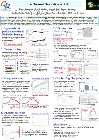
X-ray astronomy satellite Suzaku& X-ray Imaging Spectrometer (XIS) • Suzaku The 5th Japanese X-ray satellite • X-ray Imaging Spectrometer (XIS) • X-ray CCD camera onboard Suzaku • 3 Front Illuminated (FI) & 1 Back Illuminated (BI) sensors • Positional resolution • ~2’ with X-ray telescope (HPD) • High energy resolution ~140eV@5.9keV (FWHM) in Aug. 2005 (just after launch) • Equipped with a charge injection (CI) structure Suzaku satellite CCD chip of XIS
Degradation of the energy resolution The time dependence of the energy resolution @5.9keV Aug. 2005 just after launch 200 Energy resolution (eV,FWHM) May 2006 150 2×10⁸ 1.9×10⁸ 1.8×10⁸ Time since 2000-1-1 00:00:00 (s) The increase of charge transfer inefficiency (CTI) causes this degradation.
How the CTI causes the degradation ACTY ACTX Q Imaging area X-ray Charge trap caused by radiation damage in orbit 1026 pixel Q Transfer direction Energy resolution is degraded. Readout charge Frame-store region Q Q’ Q’’ Q’ Q’’ Readout node 0 ACTY
54 rows Transfer direction Spaced-row Charge Injection (SCI) Charge injection structure ACTY ACTX Charge trap caused by radiation damage in orbit Q Imaging area X-ray Injected charge fills the traps. →It decreases the CTI. 1026 pixel Q Q’ Q’’ Energy resolution is recovered! Frame-store region Q Readout charge Injected charge Q’ Q’’ ACTY Readout node 0
Spectra of onboard cal source 55Fe • We operated XIS with the SCI technique in orbit for the first time in August 2006 and verified the recovery of the energy resolution from 210eV to 150eV (@5.9keV,FWHM) no-SCI SCI Mn I Kα Mn I Kβ Pulse height (channel) • We studied the gain non-uniformity in the SCI mode and developed a new correction method for it.
How the SCI mitigates the gain non-uniformity • Perseus cluster of galaxies • It is a bright diffuse X-ray source. • It covers almost all of the FOV of the XIS. • Its spectrum has strong He-like Fe Kα line and the line center is roughly independent of the position. →Suitable for the study of the gain non-uniformity over the chip. • Aug. 2006, in the both SCI & no-SCI mode, exposure time ~50 kilo seconds XIS image of Perseus cluster
How the SCI mitigates the gain non-uniformity He-like Fe Kα from Perseus cluster • Perseus cluster ACTY Pulse Height channel ACTX He-like Fe K α cnts/ch/s Pulse Height channel The CTI became ~30% by the SCI.
The gain non-uniformity on a smaller spatial scale Positional dependence ofMn I Kα line • Ground experiment of the SCI with proton-damaged CCD 500 Transfer direction 450 Pulse Height 400 Tomida et al. 1997 Charge Injected row 350 100 200 300 400 500 Transfer pixel “Saw-tooth” gain non-uniformity appeared. → Does it appear in orbit?
Onboard calibration sources 55Fe • They irradiate the upper edge of XIS continuously. → We can use long exposure data. • The spectrum has Mn I Kα line and the line center is 5.895keV. • April 2007, in the SCI mode, exposure time ~1 mega seconds XIS image of Cal source
The gain non-uniformity on a smaller spatial scale Charge injected row • Onboard calibration source 55Fe Mn I Kα from onboard cal source Charge injected row C Pulse Height channel 54 rows B A A Transfer direction B Mn I Kα C Transfer direction cnts/ch/s Kβ ACTY PH CH “Saw-tooth” gain non-uniformity appeared in orbit.
The slope at ΔACTY=0 PH0 PH Saw-tooth function The slope at ΔACTY=54 ΔACTY 54 rows ACTY charge-injected rows Correction for the gain non-uniformity • We modeled the positional non-uniformity of the gain by “saw-tooth” function below. • Three parameters, the slope at ΔACTY=0, ΔACTY=54 and PH0 specify this function uniquely. • Fit the observed ACTY-PH relation with the saw-tooth function to obtain the the slope at ΔACTY=0, 54 and PH0, then correct the observed PH. Saw-tooth Correction
Result of the saw-tooth correction method Mn I Kαfrom onboard cal source Mn I Kαfrom onboard cal source fitting result of the saw-tooth function Pulse Height channel • The correction reduced the gain non-uniformity at 5.9 keV from ~ 0.5% to ~ 0.1% →The gain is uniform on the order of a few eV at 6 keV with this correction. • The energy resolution is also improved. 151 eV → 148 eV @5.9 keV FWHM (additional width ~ 30 eV) Without Saw-tooth correction With Saw-tooth correction
The current status of the Suzaku XIS software & data processing for the SCI • The saw-tooth correction has been built into public Suzaku analysis software and released. • Version 2.0 data processing incorporates the saw-tooth correction and the calibration of the SCI. The processing has already begun. • The calibration database for the SCI is being updated continuously now.
Summary • Suzaku XIS operated the spaced-row charge injection technique for the first time and verified the recovery of the energy resolution. • The CTI became ~30% by the SCI. The gain non-uniformity over the chip was mitigated well in orbit. • The saw-tooth gain non-uniformity was shown in orbit in April 2007. • We developed the saw-tooth correction method. It made the gain in the SCI mode uniform on the order of a few eV at 6keV. • The software for the SCI mode has been released. The data processing for the SCI mode already started.