Download
1 / 36
360 likes | 499 Vues
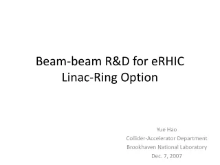
Beam-Beam Effect in eRHIC. Yue Hao May. 9, 2008. e-cooling. PHENIX. Main ERL (3.9 GeV per pass). STAR. e + storage ring 5 GeV 1/4 RHIC circumference. Four e-beam passes. Linac - Ring Scheme Design. x. y. z(s). Courtesy of V. Ptitsyn. Linac – Ring Parameter Table.

E N D
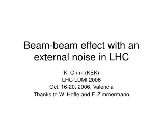
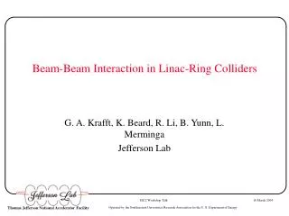
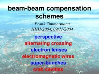
Beam-Beam Effect in eRHIC YueHao May. 9, 2008
e-cooling PHENIX Main ERL (3.9 GeV per pass) STAR e+ storage ring 5 GeV 1/4 RHIC circumference Four e-beam passes Linac - Ring Scheme Design x y z(s) Courtesy of V. Ptitsyn
Advantages of Linac-Ring Scheme • Luminosity enhancement 0.47×1033 cm-2-s-1 2.6×1033 cm-2-s-1 • Full spin transparency for all energy • Longer drift space in IR • Upgradable to higher electron energy (20GeV)
Beam-Beam field For a transverse Gaussian distribution, (+/-4 sigma cut-off) Bassetti-Erskine formular For round beam case, the field have simple form Near axis, the field is linear.
Outline of Beam-Beam Effect Study • Effect of electron beam • Disruption and mismatch • Pinch effect • Beam loss concerns • Effect of proton beam • Instability of head-tail type (Kink Instability) • Proton beam emittance growth from pinch effect • Other issues, e.g. Noise
Disruption Effects Electron beam travels from positive longitudinal position to negative. The nonlinear beam-beam force will cause the electron beam geometric emittance growth. The focusing force will attract the electron to center and form the effect so called ‘pinch effect’ Design β* = 1m, waist at IP, Initial emittance 1nm
Mismatch The mismatch due to beam-beam effect also plays a important role. It can enlarge the effective rms emittance in additional to the geometric rms emittance growth. Design β* = 1m, waist at IP, Initial emittance 1nm
Effective Emittance vs. Geometric Emittance Geometric Emittance Effective Emittance
Minimize the mismatch (Linear approach) The boundary condition of above differential equation is at the negative infinity away from IP before collision theoretically. Due to quick attenuation of proton longitudinal distribution beyond 3 rms beam length, we can set the boundary condition at the entrance of interaction region where s = 3m.
Minimize the mismatch (Linear approach) There should a design β*, which lead the beam after collision to match the optics. The β* can be solved from
Long-Tail Distribution after Collision β* =0.25m The optics of energy recovery path and linac must have large acceptance from large beam loss.
Vary the electron emittance, the optics (beta alpha function) at IP point before collision Compromise to get higher luminosity, smaller emittance after collision, and larger average electron beam size.
Luminosity and minimum beam size as function of design waist position Design β* = 0.2m, Initial emittance 5nm
Initial Beer-Can Distribution Design β* = 1m, Initial emittance 1nm Design β* = 0.25m, Initial emittance 4nm
Beer Can case for β* = 0.25m The 100% effective emittance improves 4 times (from 2e-7m-rad to 5e-8 m-rad) if the initial distribution is Beer-Can instead of Gaussian form.
Power Loss calculation Courtesy of V. Ptitsyn
Effective β* and waist Design β* = 1m at IP Initial emittance 1nm Design β* = 0.25m at IP Initial emittance 4nm
Effective β* and waist # Luminosity here is 1.5×1033
Beam-Beam effect on Proton beam • Tune shift and tune spread • Need proper working point. • (0.672, 0.678) is used in simulation. • May introduce single bunch transverse instability (Kink instability). • Beam-beam force acts as wake field. • Threshold • Possible way to suppress the emittance growth
Kink instability Use 2-Particle model to illustrate kink instability, The two particles have same synchrotron amplitude but opposite phase. Let T be the synchrotron period. p p p e p e p p p e p e e p e p p p e p e p p p After T/2, the head and tail exchange there positions p Unstable Stable p p e p e Candidacy Seminar
Threshold (Two-particle model) One turn map for two particles: Kick from the leading particle to trailing one. with After half synchrotron period Here we assume the wake field is constant. More precisely, the electron beam performs a oscillation inside the proton beam
Threshold (Two-particle model) The total matrix for one synchrotron oscillation gives: If synchrotron oscillation is slow enough and transverse tune is not too close to integer and half integer. Threshold:
Threshold and modes For fixed electron intensity (1.2e11 per bunch), the threshold of proton intensity for kink instability is about 1.6e10 proton per bunch. The longitudinal snapshot shows mode 1 pattern.
Increase tune spread to suppress emittance growth With Energy spread 1e-3
Pinch Effect on Proton Beam • Source • Electron rms beam size shrinks by proton beam. • Electron beam distribution has a dense core.
Pinch Effect on Proton Beam • Main Factors • Working Points (avoid nonlinear resonance ) (0.674,0.675) • Electron optics and initial emittance (reduce synchro-betatron oscillation) • Difference of Gaussian and Beer-Can distribution of electron beam
L=1.72 ×1033cm-2-s-1 L= 2.46 ×1033cm-2-s-1 This shows the dense core of electron beam plays a very important role in proton beam emittance growth. Large emittance and small design beta* is preferred for electron beam.
Possible electron candidates 16 seconds for emittance double (Linear fit) L=2.5×1033cm-2-s-1 55 seconds for emittance double (Linear fit) L=1.5×1033cm-2-s-1
Conclusion • We can optimize the design parameter to prevent beam loss after collision. • R&D of beam-beam effect provide information after collision for both IR design and linac design. • Kink instability can be suppressed by proper energy spread • Small beta and large emittance for electron beam is preferred for proton beam quality • More results arecoming for pinch effect.
Smoothed BeerCan Use Key points and spline interpolation instead of explicit function to represent field