Download
1 / 38
400 likes | 1.09k Vues
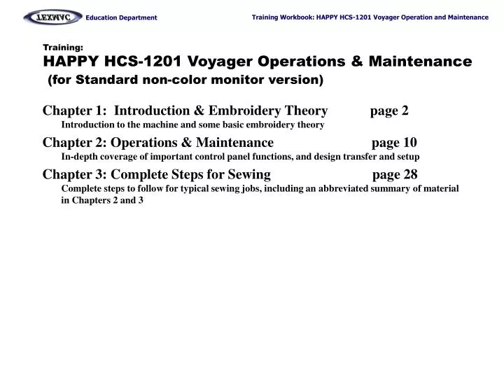
Training: HAPPY HCS-1201 Voyager Operations & Maintenance (for Standard non-color monitor version). Chapter 1: Introduction & Embroidery Theory page 2 Introduction to the machine and some basic embroidery theory

E N D
Training:HAPPY HCS-1201 Voyager Operations & Maintenance(for Standard non-color monitor version) Chapter 1: Introduction & Embroidery Theory page 2Introduction to the machine and some basic embroidery theory Chapter 2: Operations & Maintenance page 10In-depth coverage of important control panel functions, and design transfer and setup Chapter 3: Complete Steps for Sewing page 28Complete steps to follow for typical sewing jobs, including an abbreviated summary of material in Chapters 2 and 3
Training:HAPPY HCS-1201 Voyager Operations & Maintenance Chapter 1: Introduction & Embroidery Theory • Overview of your machine • Diagram of major parts • Overview of major mechanical systems • Color change system, sewing system, X-Y pantograph • Control Panel Introduction & Orientation • Adjustment / emergency stop • Power-on & navigating to the main sewing screen • Shutting down • Other Important Screens: A brief introduction • Function menu • Main menu, pages 1 and 2 • Embroidery basics & theory • About stitches, sewing quality, stitch file formats, the embroidery needle
Overview: A Quick Tour of the Machine tree Manual needle selector knob Take-up lever Safety cover Screen contrast adjustment upper-tensioning knobsthread break sensorslower tensioning knobs Thread posts base EmergencyStop Switch Ports Serial USB LAN fuses power X-carriagetubular arm Compact flash slot Rotary hook door / bobbin cover Oiling guide/instructions cylinder arm Main power switch: Press and hold continuously for 1-2 sec. to power on Table area beneath cylinder arm:: for tubular goods, table or other object under cylinder arm can provide support. For garment. However, cap driver requires that surface be at least 4” below level of feet. Chapter 1: Introduction and Basics
take-up lever “crank” cam converts spinning motion to up-and-down motion of needle bar needle bar bobbin sits in basket of rotary hook lower shaft rotary hook spins on lower shaft Side view of machine: head and sewing arm • 2. Sewing System • Take-Up Lever • Needle bar • Rotary hook / bobbin • 1. Color Change System • Moving head • Thread cut system Overview: 3 key mechanical systems Moving head Currently selected needle is the one directly over the presser foot. During a thread trim: (1) Needle descends, and thread is cut below needle plate between a fixed & moving knife. (2) Then, when needle comes back up, the “catcher” hook grabs the cut end and “docks” it into the thread holder. 3. X-Y Pantograph X-direction Y-direction x-carriage Chapter 1: Introduction and Basics
Emergency Stop • Initial Power-On Control Panel Intro: Quick Orientation This button is used to shut the machine off in case of emergency. The machine will remember the last sewn stitch but may be slightly off alignment when re-started. To recover from emergency stop, clear any problem, un-twist the button to re-set it and power on normally. The machine will not power on unless the button is re-set to the “on” position. Power on your machine with the black switch located on the side of the machine. The message below appears. Emergency Stop CAUTION!FRAME MOVE Press ENT to continue. Chapter 1: Introduction and Basics
ID: 3 Nd: 5 JOELOGO STOP • Getting to the Main Screen Control Panel Intro: Power On to the Main (Drive) Screen The FUNCTION menu This is the main “drive” screen. The machine will not sew or accept design transfers via cable unless it is in this mode. Learn how to get to this screen either from power-on or by pressing MENU. In addition to the main Drive screen, there are 2 other important menus to know: The Main Menu (shown on the next page) and the Function menu, shown below, which is accessed by pressing AND holding the MENU button. Origin Symbol: shows that the current design is at the origin and ready to begin. This is the main “drive” screen. Active needle: current needle Chapter 1: Introduction and Basics
STOP The Main Menu The other - and most important - menu is the Main Menu, accessed from the main Drive screen by pressing MENU as shown below. Control Panel Intro: Other Important Screens Pattern Needle Card Convert F Position Create Letter Other The machine can only display 2 items of the main menu at a time. Use the up and down arrows to navigate to adjacent items. PATTERNNEEDLE Chapter 1: Introduction and Basics
Key Embroidery Basics / Theory • About Stitches : • All stitches are formed by a ½ loop of colored thread looped with ½ loop of bobbin thread. • Max and minimum length: Must be between 1mm (.04 inch) and 12.7mm (1/2 inch). Too short causes thread breaks. Too long, stitches are too loose. • 3 Major Factors Affecting Sewing Quality that you can control: • Tension – once properly set, should rarely require re-adjustment. We will cover this in class. • Hooping – proper hooping is a must. Not too tight, not too loose. We will cover this in class. • Digitizing – hire a digitizing service and/or learn how to digitize in digitizing classes. • Sewing file format used in embroidery: DST • All commercial machines read this format • Does not have color information – must load the design into the machine AND tell it which colors to sew. • Limited in editability – the design must be sewn at the size it was digitized. • About Embroidery Thread • Upper (colored) thread • Can be polyester or rayon, usually polyester. Standard is 40 weight • Comes in several sizes: 5,000 meter cones to 1,000 meter cones. • Handle carefully: physical contact, oil/dirt, moisture can prevent it from unspooling smoothly and catch • Bobbin thread • L-type, approximately 350 yards per spool. Bobbin thread will have to be changed more frequently than upper thread • Lasts approximately 25,000 to 60,000 stitches Chapter 1: Introduction and Basics
Key Embroidery Basics (continued) • Embroidery Needles: • Type DB-K5, standard size is 75/11 ballpoint for most applications. Alternate needle for sewing caps and other tightly-woven goods (heavy canvas) is 80/12 sharp point for better penetration • The width of the shaft of an embroidery needle limits the the finest possible detail (the smallest possible stitch). Standard size (75/11) needles are .75 mm across, so stitches must be at least a little wider than the hole that the needle punches in the fabric (minimum distance 1mm) • Needles are subject to wear! Over time, burred surfaces and other wear can cause problems. Be prepared to change needles frequently especially with heavy use. butt Front view Side view Shank – rounded. Does not have a flat spot blade or shaft Scarf – faces towards the back of the machine Groove – allows you to find the front of the needle by feel. Chapter 1: Introduction and Basics
Chapter 2: Machine Setup, Control Panel Operation • Proper Machine Setup • Machine environment • Upper threading • Bobbin threading & Tensioning • Control Panel 2 • Sewing controls, what your machine is telling you on the main screen • Important Main Menu functions in detail: Pattern, Setting, Needle, Read, Frame, Position • Transferring Designs into the machine, detailed steps • Via Compact Flash • Via USB Chapter 2: Operations & Maintenance
Proper Machine Setup: Environment Temperature and Humidity-Controlled Environment Thread must pass up from cones through guide holes in thread tree and through every specific point along the face of the sewing head. Thread must be “docked” at the thread holder spring. Clean, protected electrical power Thread must pass up from cones through guide holes in thread tree and through every specific point along the face of the sewing head. Thread must be “docked” at the thread holder spring. Steady table/mounting surface Thread must pass up from cones through guide holes in thread tree and through every specific point along the face of the sewing head. Thread must be “docked” at the thread holder spring. Chapter 2: Operations & Maintenance
Proper Machine Setup: Upper Thread UPPER THREAD • Proper Thread Routing: All threads must be routed correctly at all points along the path through the sewing head. needle 7 needle 6 needle 8 needle 5 needle 9 needle 4 needle 10 needle 3 needle 2 needle 11 needle 1 needle 12 General Thread Route Thread must pass up from cones through guide holes in thread tree and through every specific point along the face of the sewing head. Thread must be “docked” at the thread holder spring. Layout of Cone/Needle Sequence Needle numbers are arranged right to left, lowest number to highest. Chapter 2: Operations & Maintenance
Proper Machine Setup: Upper Thread UPPER THREAD – complete route through moving head • Proper Thread Routing: All threads must be routed correctly at all points along the path through the sewing head. • Practice good thread “Discipline”: After threading all needles, ensure there is no slack anywhere along the thread path. Make sure to: • Pull all threads – to ensure thread feeds smoothly and turns the break sensor, and all slack is removed from around thread cones • “Dock” all thread ends from each needle onto the thread-holding spring. Prevents thread from coming loose and catching where not desired. Upper Tensioner Thread only makes ½ turn – make sure it passes to the left between the 2 metal discs. Thread Break Sensor Thread this like the upper tensioner – ½ turn to the left. Make sure the thread falls in the groove as shown. Lower Tensioner Thread makes 1 full turn clockwise around the base of the knob – make sure it runs in the V-shaped groove of the spoked wheel. Thread “docked” in thread holding spring Chapter 2: Operations & Maintenance
Proper Machine Setup: Re-loading/ Checking Bobbin RE-LOADING THE BOBBIN CORRECTLY The bobbin will need to be replaced frequently, allowing only 30,000 to 60,000 stitches per spool. This has to be done correctly every time. 2. Feed thread through eye at the end of the tension flap. • Ensure bobbin turns clockwise. Pull thread through this slit. 3. Pass thread under wire loop at the top front of the bobbin case. CHECKING TENSION • ·The “yo-yo” test is very exact in checking tension. Perform this quick check each time you re-load the bobbin. Practice until you are comfortable doing this. • Check bobbin tensionfrequently when changing bobbins. TAKE CARE TO RE-INSERT THE RELOADED BOBBIN CASE FULLY! Your machine will not sew any stitches unless this is done. At worst, the needle & needle bar may strike the side of a poorly-inserted bobbin case, breaking the needle and possibly putting needle depth out of adjustment for that needle. Make small adjustments – no more than a ¼ or ½ turn in either direction before re-checking tension. Chapter 2: Operations & Maintenance
Sewing Controls Basic Sewing Controls On this page, learn the function of the important sewing controls. MENU accesses the main menu or the Sewing Position sub-menu FORWARD advances sewing position forward while machine is stopped. Sewing arm movement move pantograph arm with the 4 arrow keys, hold ENT at same time for quick movement P.FOOT lowers the presser foot on command T. CUT cuts current thread and tucks end into thread holder. Needle Select Keys change the currently-selected needle while machine is stopped. Speed control – adjustsmax sewing speed. STOP stops sewing. Also when stopped moves sewing position backwards. Useful after thread breaks. START starts sewing or starts the trace. Sews in “creep” mode when held down. Chapter 2: Operations & Maintenance
Menu Screens Important Main Menu Features The options of the main menu have the most important, useful functions. ACCESSING THE MAIN MENU Main Menu Select or delete from list of patterns Pattern Needle Card Convert F Position Create Letter Other List of color changes in selected design Load from list of designs in Flash card MENU Press Jump to stitch or color change Machine default settings menu Lettering functions (do not use ! ) Setup, Clock, Thread detect setting ACCESSING DESIGN POSITIONING MENUThese are important for adjusting the sewing position in the hoop and getting to the last-sewn position MENU Press and hold Chapter 2: Operations & Maintenance
Important Menu Items Pattern - The control panel can store a maximum of 250,000 stitches of designs, or 99 designs total. From Pattern, you can choose one of the designs other than the current one, or delete any designs in memory. Needle - Designs sew in a sequence of color blocks. In order that your machine sews each color block with the correct color in the correct order, you can set that color sequence in the Needle screen, shown here. Card – Go to this menu item to read designs from a compact flash card. F. Pos – Use this option to move the sewing position to any point in the design – you can do this by stitch # or color block #. Chapter 2: Operations & Maintenance
Transferring Designs into Your Machine In this section, we provide detailed steps about the 2 most commonways to transfer a design into your machine to be sewn: • USB connection or • Compact flash card Compact Flash Card – (shown inserted into PCMCIA adapter sleeve) inserts into this slot on the side of the control panel. It works like a floppy disk or a USB jump drive: connect the Flash card to a computer, save the design onto the flash card, and insert the flash card into the machine. USB port is found on side wall of machine with other ports. You can connect a Windows PC to the machine with a USB cable so you can transfer designs and perform other functions. • On the following pages, we’ll go over the steps for both methods in detail. Next: USB connection Chapter 2: Operations & Maintenance
check “compatible” set to 12 needles set to USB no borer Transfer via USB Connection 2. Wait for this screen to appear. One-Time Set-up of the USB Connection (continued from last page)Follow the 11 steps on these pages to set up your PC for a USB connection. You’ll only need to do this once. 3. Click here to install the HAPPYLINK transfer program. 1. Run the CD that came with your machine before connecting your HAPPY machine to your computer. 4. Click here to install the USB driver if your PC has Windows 2000, XP or Vista. 6. Click on File…Options until the dialog box shown below appears. Ensure that the dialog box is set as shown below, then click OK. 5. Launch the HAPPYLINK program you installed in Step 3. HAPPYLINK program window Chapter 2: Operations & Maintenance
Transfer via USB Connection 5. Ensure that your HAPPY machine is turned off, and connect a USB cable between your PC and the machine. You may use the cable that came with your machine or purchase a longer one at any computer supply store. Ensure that any USB cable you purchase is high-quality and under 16 feet. One-Time Set-up of the USB Connection (continued from last page)Follow the 11 steps on these pages to set up your PC for a USB connection. Connect USB cable to any USB port on your PC. USB port 7. Continue through the prompts, ensuring that at some point, Windows identifies the new hardware as “02 Happy Embroidery Machine” as shown below: 6. Power on your HAPPY machine and watch your PC screen. Windows should detect the machine, starting the Hardware Installation Wizard, similar to what is shown below. • Click “no not at this time” if the prompt ‘do you want Windows to search the Internet for drivers’ • Check “continue anyway” if you receive a message saying that “the software for this hardware has not passed Windows Driver Signing Testing” • Continue until the message “Your new hardware is installed and ready to use” or a similar message appears. Chapter 2: Operations & Maintenance
Transfer via USB Connection 11. Launch the HAPPYLINK program again. If you’ve done everything correctly, the USB connection indicator should appear as a solid grey icon in the top-left corner of the program bar as shown below. One-Time Set-up of the USB Connection (continued from last page)Follow the 11 steps on these pages and the next to set up your PC for a USB connection. USB connection indicator NEXT: Actual Steps to Transfer a Design by USB Cable Chapter 2: Operations & Maintenance
Transfer via USB Connection 1. Ensure that the machine is powered on and at the main (drive) screen. Your PC will only be able to transfer designs from this screen. 2. Connect the USB cable between machine and PC if you haven’t already done so. Actual Steps to Transfer a Design by USB Once you’ve properly set up HAPPYLINK and the USB drivers on your PC,you’ll only need to follow the 5 steps on this page to actually transfer designs. This is the main (drive) screen. 3. Your design will appear here. Click once to highlight it and click OK. • Choose format here (either DST or TAP – the machine will read both.) 2. Browse here to the folder where your design is saved. 3. Launch the HAPPYLINK program and check to ensure the USB icon is lit. 4. Open your design by clicking on File…Pattern Open. The above dialog box appears. Follow the directions indicated above, and your design should open (in grey tones) into HAPPYLINK. 5. Click the Send Pattern Icon. The design will transfer from your PC to the machine. Send Pattern icon Chapter 2: Operations & Maintenance
Transfer by Compact Flash Card What to Buy The slot located on the side of the machine’s control panel accepts flash memory cards, to allow you to transfer designs into memory from a computer. To do this, you’ll need to buy the 3 items shown on this page from most stores that sell computer or digital camera supplies. 3. USB to compact flash card reader – needed if your PC does not have a PCMCIA slot. (most don’t, though some laptops have one). Allows you to connect your card to a computer and save designs to it. • PCMCIA Adapter – Allows the card to fit into the machine’s flash card slot. For PC’s (some laptops) that also accept PCMCIA cards, there is no need for (3) the USB to compact flash adapter. NECESSARY. • Compact Flash card – This is the memory card itself. Your machine accepts compact flash cards up to 1 Gigabyte in size. NECESSARY. NEXT: ALTERNATE FORMS OF FLASH MEDIA Chapter 2: Operations & Maintenance
Transfer by Compact Flash Card Other Types of Flash memory (What not to Buy) Your HAPPY machine was designed to accept other types of Flash cards, but none have worked as successfully as Sandisk-brand compact flash cards. For your assistance, we’ve identified other types of flash memory cards available below. We have attempted to show the cards approximately to scale with each other. Note that compatibility with these types may improve as revisions of the machine’s on-board firmware and hardware are released. GOOD Other brands of compact Flash card: Some other types work, although not all. SanDisk brand Compact Flash card: This has worked with the greatest success with HAPPY machines, and is widely available. Memory Stick: This has been the least successful of the other Flash media types SD Card: Few brands of this type have been found to work. Other Types of Adapter Sleeves: All-in-1 adapter sleeves have had limited success, even Sandisk brand. SmartMedia Card: Few brands of this type have been found to work. NEXT: HOW TO USE YOUR COMPACT FLASH CARD Chapter 2: Operations & Maintenance
To computer To computer USB reader PCMCIA card or • Choose format here (either DST or TAP – the machine will read both.) 3. Your design will appear here. Click once to highlight it and click OK. 2. Browse here to the folder where your design is saved. Transfer by Compact Flash card How to Use Compact Flash Cards to Transfer Designs Follow the 9 steps on these pages to transfer designs from a PC into your HAPPY machine with a Compact Flash card. • Connect the Compact Flash card to your computer. Insert the card into a PCMCIA adapter (if your laptop has this type of slot) or otherwise insert it into the USB reader. • Start HAPPYLINK and open the design you wish to transfer from File… Pattern Open. You’ll see the dialog box below appear. Follow the directions. Chapter 2: Operations & Maintenance
Transfer by Compact Flash card 4. Save the file to the Compact Flash card. Click on File…Save As. The dialog box shown below appears. Follow the directions below to save, then close HAPPYLINK. 3. (optional step) Set the color sequence. Click on the icon shown below to do so. Or if you choose, you can set colors in your machine. How to Use Compact Flash Cards to Transfer Designs Follow the 9 steps on these pages to transfer designs from a PC into your HAPPY machine with a Compact Flash card. • Click on Safely Remove Hardware Icon to shut off the card. You’ll find this icon at the lower-right edge of the screen near the clock. Continue until the message “It is now safe to remove” appears. Chapter 2: Operations & Maintenance
Transfer by Compact Flash card How to Use Compact Flash Cards to Transfer Designs Follow the 9 steps on these pages to transfer designs from a PC into your HAPPY machine with a Compact Flash card. 7. Go to the Card screen in the control panel to read the card. From the main (drive) screen press MENU and use the arrow keys to go to CARD and press ENT. 6. Insert the Flash card into the machine. You’ll need to insert the card into the PCMCIA adapter sleeve. Release tab pops out when the card is inserted fully. 8. Find your design in the list. Any DST & TAP designs will show automatically in a list. Choose your design with the blue arrow keys and press ENT. Insert card fully into slot until it snaps softly into place. 9. Press ENT to return to the main (drive) screen. Once the design is imported from the CARD screen, press the ENT button until you’ve returned to the main Drive screen, where image of your design should now appear. (The next step will be to set the colors in the Needle screen.) NEXT: CHAPTER 3: COMPLETE STEPS IN A TYPICAL SEWING JOB Chapter 2: Operations & Maintenance
Chapter 3: The Complete Steps for a Typical Sewing Job Use this section as a condensed, all-in-one reference for all the steps involved in a typical sewing job. Be sure to follow the topics in order as listed. • Machine Set-Up Checklist • Design • Backing & Hoops • Machine prep • Design Transfer: Complete steps • USB • Compact Flash card • Design Set-Up • Setting color sequence with the “needle” screen • Matching and locating within a hoop with the “frame” screen • Hooping • Frame Trace • Verifiying fit and position within the hoop • Sewing • Sewing: Setting sewing speed • What to look for to refine your sewing run • Handling interruptions: thread breaks, replacing bobbin thread, returning to sewing position • A practical, live example: running a tension test design • An illustrated example (tension test design) of sections 1-4 using an actual design
1. Pre-Prep Checklist Follow this advance prep checklist before any sewing job: • Machine Prep: Threaded and Oiled • Properly oiled. At the very least, ensure 1 drop of oil on the rotary hook. • Bobbin properly threaded. New bobbin, properly threaded, and tensioned. Ensure that thebobbin case is inserted FULLY into the rotary hook. • Upper thread properly threaded. • Are all the colors for the design installed on the machine? If this is a production job, use quality, well-cared-for thread cones. Also ensure that you’ve checked with your customer on any specific colors. • Are all colors properly threaded ? Ensure that at least the threads being sewn are threaded correctly at all points (thread feeds smoothly between metal disks of upper tension knob, spins the sensor wheel and lower tensioner wheel. Pull any loose, slack thread out from any thread, especially around the thread cones. Additionally, all thread ends should be docked in the thread holder behind the needles or in the thread holding spring. • Design Prep • The digitized design: Be sure to check the following: • Was it digitized specifically for the material or garment you intend to sew on? If not, be prepared to run at least 1 test run to check for quality. Different fabrics and garments sometimes require different digitizing techniques. Stock designs, for example, may sew well on 1 garment type but not another. • Know the design size. We’ll go over this later in this chapter. But remember, designs can sometimes be scaled from their original size, but not always. It is always best if the design was created for the intended sew size. • Color sequence: be sure that you know the color sequence of the design, which should be provided by the digitizer, the stock design catalog, or if you are the digitizer, get this from the software that you created it in. • Other Sewing Material Prep • Hoop: Choose the smallest possible hoop that fits the design with some room to spare. If the design barely fits, go to the next larger size. • Backing and other material: Have the appropriate backing, topping or other material ready. You can read more about this in Chapter 5: Additional sewing options. Chapter 3: Complete Steps for Sewing a Typical Job
ID: 3 Nd: 5 JOELOGO STOP 2. Getting the Design in to the Control Panel 1. Ensure that the machine is powered on and at the main (drive) screen. Your PC will only be able to transfer designs from this screen. 2. Connect the USB cable if you haven’t already done so. Steps to Transfer a Design by USB Follow these steps to transfer your design by USB cable. 3. Your design will appear here. Click once to highlight it and click OK. • Choose format here (either DST or TAP – the machine will read both.) This is the main (drive) screen. 2. Browse here to the folder where your design is saved. 4. Open your design by clicking on File…Pattern Open. The above dialog box appears. Follow the directions indicated above, and your design should open (in grey tones) into HAPPYLINK. 3. Launch the HAPPYLINK program and check to ensure the USB icon is lit. 5. Click the Send Pattern Icon. The design will transfer from your PC to the machine. Send Pattern icon Chapter 3: Complete Steps for Sewing a Typical Job
To computer To computer USB reader PCMCIA card or • Choose format here (either DST or TAP – the machine will read both.) 3. Your design will appear here. Click once to highlight it and click OK. 2. Browse here to the folder where your design is saved. 2. Getting the Design in to the Control Panel Steps to Transfer a Design by Compact Flash Card Follow the 9 on these pages to transfer your design by Flash card. • Connect the Compact Flash card to your computer. Insert the card into a PCMCIA adapter (if your laptop has this type of slot) or otherwise insert it into the USB reader. • Start HAPPYLINK and open the design you wish to transfer from File… Pattern Open. You’ll see the dialog box below appear. Follow the directions below. Chapter 3: Complete Steps for Sewing a Typical Job
2. Getting the Design in to the Control Panel Steps to Transfer a Design by Compact Flash Card Follow the 9 on these pages to transfer your design by Flash card. 4. Save the file to the Compact Flash card. Click on File…Save As. The dialog box shown below appears. Follow the directions below to save, then close HAPPYLINK. 3. (optional step) Set the color sequence. Click on the icon shown below to do so. Or if you choose, you can set colors in your machine. • Click on Safely Remove Hardware Icon to shut off the card. You’ll find this icon at the lower-right edge of the screen near the clock. Continue until the message “It is now safe to remove” appears. Chapter 3: Complete Steps for Sewing a Typical Job
2. Getting the Design in to the Control Panel Steps to Transfer a Design by Compact Flash Card Follow the 9 on these pages to transfer your design by Flash card. 6. Insert the Flash card into the machine. You’ll need to insert the card into the PCMCIA adapter sleeve. 7. Go to the CARD menu in the control panel to read the card. From the main (drive) screen press MENU and press the arrow keys to go to the CARD option and press ENT. Release tab pops out when the card is inserted fully. Insert card fully into slot until it snaps softly into place. 8. Find your design in the list. Any DST & TAP designs will show automatically in a list on the right. Choose your design with the blue arrow keys and press ENT. 9. Press MENU again to return to the main (drive) screen. Once the design is imported from the CARD screen, press the MENU button until you’ve returned to the main Drive screen, where name of your design should now appear. (The next step will be to set the colors in the Needle menu.) Chapter 3: Complete Steps for Sewing a Typical Job
3. Setting Design Colors & Settings • Press MENU and arrow down or up to NEEDLE. Then press ENT to enter the Needle screen. • A list of color block numbers appear. If the design’s colors have never been set up, all color blocks will be assigned needle “0”.| • Choose a color block using the up- and down- arrow keys • Assign that block a needle number using the left and right arrow keys. • Arrow up or down to the next color block and repeat the procedure until you’ve assigned a needle number to all of the color blocks. How to Set the Color Block Sequence for A Design: Follow steps 1-5 on the right to set the color sequence for a design. When finished, press MENU to return to the main menu, and then MENU again to return to the main sewing screen. Follow the steps on this page to set the color sequence for the design. Chapter 3: Complete Steps for Sewing a Typical Job
4. Hooping • Choose the smallest hoop that will fit your design. This results in better-quality sew-outs, but ensure that there is at least a little extra room in the hoop as a safety margin. • Choose an appropriate backing or stabilizer for the garment and the design. Depending on how stable or “stretchy” the garment is, you may need heavier, more stable backing (i.e. 1-2 layers of heavy cutaway) or lighter backings (simpler tear-away) • Align the garment straight in the hoop – In order for the design to sew level, the garment needs to be hooped level. As mentioned in Chapter 1, hooping contributes heavily to sewing quality. Be sure to follow these guidelines when hooping a garment. Tighten the garment in the hoop by pulling evenly on all sides. Inner ring garment backing outer ring Get the right amount of tension on the garment:Too tight – hoop leaves “burn marks on the garment. Too loose – garment will “pucker” as more stitches are sewn onto it. Adjustment screw compensates for different garment thicknesses. Chapter 3: Complete Steps for Sewing a Typical Job
5. Checking Fit and Position in the Hoop At this stage, you’re almost ready to begin sewing. First, it’s also important to verify that the design fits using the Trace. Follow the steps shown below. 1. Go to the main Drive sceen. 2. Ensure that the design is at the Origin point by checking that the origin symbol is showing. If you need to return to the Origin, hold MENU until the menu shown at the right appears, then press the right arrow key to return to origin as indicated by the screen. 3. Press START to let the machine begin tracing. The hoop will begin to move, and the presser foot will “point” to where the edges of the design will sew. Check to ensure that the design does not sew near the edges of the hoop. You can hold the START button to slow the trace movement. 4. If not satisfied with the location, return to the Origin by holding the MENU key down and pressing the right arrow key as in step (2) above. This symbol indicates that to return to the Origin, press the left arrow key. 5. Move the design by moving the arrow keys. 6. Go back to step 3 and repeat if desired. You can watch the trace as many times as you wish until you’re confident that the machine will clear the hoop. Chapter 3: Complete Steps for Sewing a Typical Job
6. Sewing If you’ve followed all the previous steps carefully, just press START to begin sewing. While the machine should continue to sew until the design is finished, watch the sew-out, especially if you are just learning, and follow the guidelines on this page. • Set the machine’s top speed with care. While your machine is capable of sewing at top speed on a regular basis, consider these general points: • Use top speed only when absolutely necessary to ensure longer machine life. • Higher speeds increase peak tensions on thread causing the design to sew more tightly than normal, and increase the risk of thread breaks • Set machine speed based on your vibration and noise tolerance. Depending on the mounting surface where you’ve installed your machine, you may find some speeds more “ideal” than others. • Watch the design carefully to check for problems. This is important if you intend to run a large number of designs on the machine. Look out for: • Efficient digitizing – are all unnecessary color changes eliminated? Was the design created in the most efficient sequence? • Thread breaks that crop up in the same spot – this is something that can be fixed with Stitch Sweeper on later runs. • Quality of the sew-out – quality problems can be fixed with adjustments to tension, hooping, or in fixing the design in a digitizing program. Chapter 3: Complete Steps for Sewing a Typical Job
7. An Example: Sewing a Tension Test Design A useful example is to sew a tension test, which not only walks you through the complete process of sewing a job, but also accomplishes the task of helping you adjust the tension on the upper (colored) thread. Follow the steps in this exercise to (1) to sew the design, then (2) adjust tension accordingly until tension is properly adjusted. • Transfer the tension test design called “H Test” into your control panel. You can download thisfrom www.happyemb.com in the Service section. • Ensure that the bobbin tension has been set correctly using the drop test. • Set the color sequence In the Needle screen to 1, 2 ,3 ....etc to 12 • Hoop an ideal fabric (2 layers of cutaway backing is usually good enough) • Sew a sample on the 32 cm square hoop. • Examine the results by flipping the embroidery over. Check each stripe to ensure there is a white strip of bobbin thread approximately 25% to 33% of the total width of the satin stitch, centered, for each color sample. • Colored thread is too loose if, on a given stripe, the bobbin thread strip is very thin or non-existent • Colored thread is too tight if, on a given color, the bobbin thread strip is wider or full-width • Adjust the tension knobs accordingly: • Make major adjustments using the upper tensioner (it places the initial gross tension on the thread. • Make finer adjustments with the lower tensioning knob, but do so 2-3 full turns in either direction to effect a noticeable difference. • Re-sew the tension test design again in a different spot on the same hooping and compare, then repeat this procedure until you're confident that all threads are sewing consistently at correct tension. Chapter 3: Complete Steps for Sewing a Typical Job