Download
1 / 38
380 likes | 537 Vues
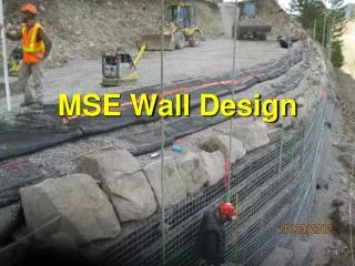
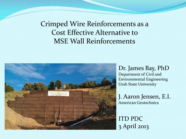
Crimped Wire Reinforcements as a Cost Effective Alternative to MSE Wall Reinforcements. Dr. James Bay, PhD Department of Civil and Environmental Engineering Utah State University J. Aaron Jensen, E.I. American Geotechnics ITD PDC 3 April 2013. Purpose.

E N D
Crimped Wire Reinforcements as a Cost Effective Alternative to MSE Wall Reinforcements Dr. James Bay, PhD Department of Civil and Environmental Engineering Utah State University J. Aaron Jensen, E.I. American Geotechnics ITD PDC 3 April 2013
Purpose • To test steel wire mats with extensible characteristics in a full-scale MSE wall • To make an observation of how the wall behaves; in an active state or at some at-rest condition • To further expand MSE wall understanding and technology • To provide a MSE reinforcement product that will be effective and lower costs • To provide the industry with a reinforcement material that will load to an active state without the negative effects of creep
K Value for AASHTO Design • kr = K * ka • K is an index for active state behavior or at-rest behavior • K value determines factors applied to loads dependent on reinforcement type Fig. 11.10.6.2.1-3 AASHTO Bridge Design
Yielding to an active state requires small wall deflections of 0.1% - 0.2 % of the wall height* For a 20 ft high wall that is only deflections of 0.25 in.- 0.5 in. The deflections must increase progressively as the wall is constructed *Boneparte, R.A. (1988). Reinforcement extensibility in reinforced soil wall design, Kluvwer Academic Publishers, London. Clough, G.W., and Duncan, J.M. (1991) “Earth Pressures” Foundation engineering handbook (2nd ed.) H.Y.Fand & V.N. Reinhold, New York, pp 224-235.
Crimped steel bars provide the required extensibility Overburden pressure Crimped steel W3.5 Wire
Crimp Behavior • Crimps do not decrease the ultimate load if bend radii conform to AASHTO specs (Suncar, 2010) • Crimps stiffen as deformation progresses • Crimps do not creep like geosynthetics • 2-3 crimps in a bar provide sufficient extensibility • Allow the soil to carry more stress than an inextensible wire mat
General Wall Design • Design based on AASHTO LRFD method • Crimped steel wire reinforcements were assumed to behave as a fully extensible product (kr=ka) • External and global stability requirement were met according to specifications
Summary of Wall Design • Longitudinal wire spacing = 16 in. • Transverse wire spacing = 24 in. • Lift thickness = 2.0 ft with 1.0 ft compaction lifts • Soil friction angle, f = 38 • Soil unit weight, g = 120 pcf • kr = ka (extensible) • No sacrificial steel (temporary wall) • W5.0 wire mats in bottom half of wall • W3.5 wire mats in top half of wall
Instrumentation • W 3.5 and W 5.0 wires are too small to easily attach strain gages • Constructed “Dog Bone” style force sensors • Each sensor uses a complete Wheatstone bridge: 2 axial gages and 2 Poisson’s gages • Each sensor was individually calibrated • Mat wires were cut, and sensors clamped to mats
Wall Construction • Constructed at Utah State University in an abandoned sand and gravel pit • Constructed from August 9 – 13, 2011 • Utilized separate, heavier gage face mats
Force Measurement Summary • Successfully measured Tmax for each mat • Lost only 1 out of 48 sensors during construction, and it was a redundant sensor • Post construction there has been some additional sensor loss, and possible baseline shift • Monitoring continued through summer 2012
Deflections Summary • Achieved target deformations of 0.25 in. – 0.5 in. • Deformations progressed during construction • Deformations from the first two lifts above a mat were greater than what was required to achieve an active state • No appreciable long-term deformations were measured • Wall was exhumed during summer 2013 and each crimp deflection was measured
Definition in AASHTO Commentary (C11.10.6.2) • “Inextensible reinforcements reach their peak strength at strains lower than the strain required for the soil to reach its peak strength.” • “Extensible reinforcements reach their peak strength at strains greater than the strain required for the soil to reach its peak strength.” • Crimped reinforcement clearly satisfies this criterion for extensible reinforcement.
AASHTO Code Only Differentiates Between “Metallic” and “Geosynthetic” Reinforcement
Summary of AASHTO Comparisons • AASHTO significantly over-predicts tension except at the top of the wall • Designing for extensible reinforcement results in significantly lower design tensions than for inextensible reinforcement
The K-Stiffness Method • Empirical approach based upon measurements in a wide variety of walls • Uses non-triangular pressure distributions, similar to those for braced and tied-back excavations, to predict reinforcement tension • Pressure distributions are based upon the stiffness of wall elements
Summary of K-Stiffness Predictions • The K-Stiffness method predicts measured reinforcement tension more accurately than AASHTO • Crimps in the USU wall decreased the reinforcement stiffness by 85%, resulting in a 40% decrease in tension in the reinforcement compared to un-crimped mats • Crimped steel wire reinforcement (semi-extensible reinforcement) is slightly stiffer than geosynthetics, but much more flexible than conventional metallic reinforcement
Observations Regarding USU Wall • CRIMPS WORK!!! The wall behaves like a wall with extensible reinforcement • AASHTO generally over-predicted reinforcement tensions. • The K-Stiffness method better predicted reinforcement tensions ~
Continuing Work • Constructing and possibly instrumenting permanent or temporary walls using crimped wire mats to develop additional case studies • Modifying crimp geometry to reduce deformations at low tension
REFERENCES AASHTO. (2010). AASHTO LRFD Bridge Design Specifications (5th ed.). American Association of State Highway and Transportation Officials, Washington D.C. Allen, T. M., & Bathurst, R. J. (2003). Prediction of Reinforcement Loads in Reinforced Soil Walls. Washington State Department of Transportation, Seattle, WA. Bonaparte, R., & Schmertmann, G. (1988). “Reinforcement extensibility in reinforced soil wall design.” The Application of Polymetric Reinforcement in Soil Retaining Structures, P. Jarret & A. McGown, edo., Kluwer Academic Publishers, Norwell, 409-457. Suncar, O. (2010). Pullout and Tensile Behavior of Crimped Steel Reinforcement for MSE Walls. Utah State University, Logan, UT. Yannas, S. F. (1985). Corrosion Susceptibility of Internally Reinforced Soil-Retaining Walls. FHWA RD-83-105. Federal Highway Administration, U.S. Department of Transportation, Washington D.C.