Download
1 / 37
370 likes | 377 Vues
Learn about the Jindalee Over-The-Horizon Radar (JORN), a world-class HF surveillance system delivered by Lockheed Martin in collaboration with Australian companies, showcasing their capability for large-scale complex projects like the SKA. Explore the historical summary, scope, and subsystems of the JORN project.

E N D
Lockheed Martin Australia Australian Industry Capability Relevant to SKA Project Challenge Noel Wainwright 4 October 2011 Picture 1 2 January 2020 Lockheed Martin Proprietary Information Lockheed Martin Proprietary Information
JORN – An Exemplar of Science/Industry Collaboration in Delivering Cutting Edge RF Technology Hypothesis • Australian companies have a proven capability to deliver large scale complex projects such as SKA Exemplar • Jindalee Over-The-Horizon Radar project - JORN - is a world class HF surveillance system delivered by Lockheed Martin acting in a joint venture arrangement with Tenix (in the decade 1993 to 2003): “RLM” • At its peak, the JV employed 650 staff in the key systems engineering, software development and systems integration disciplines • A crucial ingredient for the success of JORN was the ability of the company to access capabilities of the parent company technologies including the assignment of 60 specialists into the program
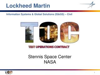
JORN Overview Historical Summary
- Transponder - Vertical Incidence Sounder - Oblique Incidence Sounder Jindalee Operational Radar Network (JORN) Nhulunbuy Christmas Island Horne Island Humpty Doo RAAF Scherger Kalumburu Groote Eylandt Hughes Lynd River Broome RAAF Curtin Kalkarindgi Normanton South Headland RAAF Learmonth JFAS Longreach Boolathana Ajana Laverton MIF RAAF Edinburgh
Overview of JORN Scope • Development of a networked radar system • 90 degree radar centered near Longreach in Queensland • 180 degree radar centered near Laverton in Western Australia • 17 remote beacon sites on Australian Coastline and Christmas Island • Operations Center located on RAAF Base Edinburgh, South Australia • Includes all building & construction works • Support facility • Located at RAAF Base Edinburgh, South Australia • Software Maintenance • Operator Training • Maintenance & Support for 46 months after acceptance
JORN Systems and Subsystems (Part I) • Each Surveillance Segment is comprised of a transmit and a receive site and contains • A Radar System • An FMS System (Frequency Management System – a TX & RX systems comprising of a Backscatter Sounder, Mini Radar, Passive Channel Evaluator and Background Noise & Signal Monitoring systems ) • A Receive Site Operations Centre • The Radar System has • A Transmit Subsystem • A Receive Range Processing and Beamforming Subsystem • A Radar Signal Processing Subsystem
JORN Systems and Subsystems (Part II) • The Frequency Management System has 8 Subsystems • BSS/MR Transmit Subsystem • Backscatter Sounder (BSS) Receive Subsystem • Mini Radar (MR) Receive Subsystem • Oblique Incidence Sounder (OIS) Subsystem • Vertical Incidence Sounder (VIS) Subsystem • HF Spectrum Monitor (SM)/HF Background Noise Monitor (BN) Subsystem • Passive Channel Evaluation (PCE) Subsystem • Transponder Subsystem
JORN Systems and Subsystems (Part III) • The other major systems and subsystems are: • Operations Centre System (Ops Centre) • Maintenance Subsystem • Software Support and Training Facility Subsystem (SSTF) • Local Area Communications and Services Element (LAC) • Wide Area Communications Subsystem (WAC)
Radar 1 Transmit Site (Queensland) • Located 30 kms South West of Longreach • Accommodates ~ 10 M&S staff • 30 high power amplifiers (20kw each) • Four log periodic antenna arrays • (high band, low band, FMS, FMS ext) • 21 km of 3 inch coaxial feed cable • 300,000 square metres of galvanized earth-mat
Radar 1 Receive Site (Queensland) • Located 185 kms South West of Longreach • Both terrestrial and satellite communications capability • 3.5 Km array • 480 Dipoles for Radar • 16 Dipoles + omni for FMS antenna • Sited to within 2mm • 20 Bunkers hold 24 Receivers each • 100s of kilometers of optical fibre and coaxial cable
JCC (Edinburgh AFB, Adelaide, SA) • Headquarters for RAAF unit 1RSU • Qld, WA and JFAS all controlled from this facility • Both terrestrial and satellite communications capability • 22 JORN Operator positions • Also home to JORN Software Support and Training Facility
Melbourne Integration Facility (MIF) Most advanced software development and integration facility in Australia Capacity for 350 engineers 20,000 sq. ft. of integration & test laboratories Extensive computing & communications infrastructure Classified laboratory capable of accommodating multiple projects Satellite communication links to South Australia & remote sites Built a World Class Engineering Facility
JORN Pre RLM • DSTO built the experimental JFAS Radar in 70s / 80s • Defence issued RFP for an operational system in ‘88 • Contract Awarded to Telstra in 1990 • Original delivery date was June 1997 • Project was in trouble from the start
Formed the Team - Employed the People • Hand Picked Telstra engineers and support team from Melbourne and Adelaide (~200) • Telstar software and support team (150) • Lockheed Martin Secondees (45) • Tenix Secondees (7) • Kept the best contractor staff (50)
Redirected Software Development • All software development effort was stopped • 7 “initiative” teams formed to address : • Requirements, Interfaces, Processes, Development environment, Software Test, Earned Value, Middleware • Team recommendations factored into the new plan • Software deliveries structured to the Integration Plan • Full set of BOEs developed and EV program adopted
Built final software product, termed Pedigree software, to RLM process Contained new architecture base for final delivery. Incorporated SPRs from Legacy integration. Software Completion Strategy Legacy Software – Integration Team Marconi Legacy Software Baseline Early 2000 SPRs Pedigree Software – S’ware Team Heads of Agreement Integration Drops Production Software - (Integration)
Established an Integration and Test Plan • Established the Melb Intgrtn Facility: • Size to rebuild 1M SLOC in < 6 hours • Allow concurrent integration and concurrent requirements verification • Built/bought integration tools • Established remote debug to site • Verify the radar operations from the MIF • Established longevity / stability program • Established test strategy with customer
UNIX Rational APEX Toolset – Ada 95 development MATLAB Modeler - Algorithm modeling Eaglespeed - Project CM Greenhills - 68040 Ada95 Development Environment WinNT Microsoft Office suite and Microsoft Project Microsoft SQL Server for Requirements Management and Test / Integration Database Labview for Test Support Items Installed the Project Infrastructure
Established a Requirements Baseline • Agreed the Network Specification with the CoA • Established a single requirements repository • Completed Software requirements scrub • Completed Systems Engineering Second Pass (SE2P) • Completed Requirements Traceability • Completed Algorithm Definitions • Established a Network Level RTEM
CSCI SLOC Comms 10,990 FMS Control 25,622 FMS Support 71,207 Stage 2 Signal Processing 18,291 Network Management 61,530 Radar Management 51,132 Coordinate Registration 20,924 Tracking 31,691 Consoles 337,759 Maintenance Console 115,102 C&CS 83,989 RxATE 20,853 Simulator 46,010 Reuse 166,994 Transmit Control 41,600 Receive Site Control 15,286 BSS Receive Processor 19,511 Transponder 27,100 Waveform Generator 22,922 Mini Radar 4,460 BN/SM Processor 5,285 Passive Channel Evaluation 4,396 Stage 1 Signal Processing 14,970 VME 35,819 Total 1,253,443 JORN Final SLOC Count
On-Site System Integration and TestMarch 1999 – October 2002
Legacy Software used to Integrate the hardware Integrated on-site to wring out Subsystem design and hardware issues Hardware Integration Strategy Legacy Software – Integration Team Marconi Legacy Software Baseline Early 2000 SPRs Pedigree Software – Software Team Heads of Agreement Integration Drops Production Software - (Integration)
On-Site Integration Program • Concurrent integration/test across 4 radar sites • Site shifts : Two 12 hour shifts/day, 7 days/week at each site • Site rotations : 2 weeks on/one week off on RDO • Effort required 12 teams of 3-4 people • Each shift required a “lead”, total of 12 shift leads • Each site had 2 leads to coordinate the shift teams and between the sites • Handover between teams was sometimes only minutes at the airport • Flights very restricted, In on Tuesday, out on Thursday at WA • Families not allowed on site • Many staff did site rotations for 3-4 years Communication was difficult but essential for success!
(1) Hardware C/O (2) Hardware C/O (5) JCC Install (4) Pedigree Install (3) Pedigree Install Integration Strategy Radar 1 Queensland Radar 2 Western Australia JCC MIF • Conducted pre-Site integration in MIF • Conducted Hardware checkout with Legacy Software at both sites • Targeted initial Pedigree site activities to WA • Transitioned Pedigree to builds to Qld following initial I&T • Maintained QLD & WA on Legacy to support ongoing hardware testing • Transitioned WA & QLD to Pedigree after baseline stable/proven • Installed JCC after Segment/MIF integration completed
JCC Integration • JCC Ops Centre equipment : • 22 Alpha Unix workstations for Consoles CSCIs • 10 Alpha Unix 4100 and 1200 Servers for Ops Centre System CSCIs • Software Support and Training Facility equipment • 8 Alpha Unix workstations for Training Facility CSCIs • 10 Alpha Unix workstations for Training Facility CSCIs • 25 NT/Unix workstations for Software Support • 5 VME Bins configured with embedded processors and interface cards for Software Support of the embedded CSCIs • Shared • Various Comms Cabinets and equipment
Transmit Site Integration • Radar Transmit • High Band and Low Band Antenna Arrays • 28 Radar High Power Amplifiers • 28 VME Bins for Waveform Generation • 2 VME Bins for Transmit Control • Alpha Servers for Transmit Control • FMS Transmit • FMS Antenna Arrays • Up to 2 FMS High Power Amplifiers • Up to 2 VME Bins for FMS Waveform Generation • Alpha Servers for FMS Tx Control • 2 VME Bins for Transmit Control • Shared • Two racks of Time and Frequency Standard Equipment • Various Alpha Servers and NT boxes for File Servers and Maintenance Consoles • Various Communications Racks and Equipment
Receive Site Integration • Radar Receive • 3.2 Km array of 480 dipoles at Radar Site 1 • 2 – 3.2 Km arrays of 480 dipoles at Radar Site 2 • 20 (at R1) or 40 (at Rs) Bunkers each containing 24 Receiver Front Ends • 68 VME Bins for Stage 1 Signal Processing • 4 VME Bins for Receive Site Control • 9 Racks of Receiver Front Ends for FMS Receive Subsystems • 2 Alpha Servers for Receive Site Control • FMS Receive • FMS Antennas • FMS Bunkers • 9 VME Bins for FMS Receive Subsystems • 2 Alpha Servers for FMS CDP • Receive Site Ops Centre • 5 Alpha Unix workstations for Consoles CSCIs • 5 Alpha Unix 4100 and 1200 Servers for Ops Centre System CSCIs • 3 Alpha Unix 4100 Servers for Stage 2 and Radar Control CSCIs • Shared equipment • 5 Cabinets of RxATE equipment • Two racks of Time and Frequency Standard Equipment • Various Alpha Servers/NT boxes for File Servers and Maintenance Consoles • Various Communications Racks and Equipment
VME Summary • In 233 VME racks there are: • 233 Dy-4 144 Single Board Computers • 103 DY-4 Serial Interface Cards • 225 Ethernet Cards • 715 Mercury MCV6 Quad I860 DSP VME Boards • 160 VMIC Shared Memory Cards • 36 FDDI Interface Cards • 84 Event Generator Cards • 24 BCIB Interface Cards • 1078 Receiver Backends
Acceptance Program Planning • Project focus turned to Acceptance of the supplies with the CoA following Marconi Descope negotiations • MoMAP Negotiations • Agreed to eliminate redundant testing • Agreed to electronic delivery of CDRLs • Clarified Warranty and latent defect provisions • Agreed to SPR carry over process • ACPP – Formalized the Criteria for Release points • June 99 - Technical Reviews and Audits Status Agreed • Sept 99 - Drawing Tree Agreed • Nov 99 - Doc Tree Agreed
Network Segment 2 Segment 1 Facilities PM ILS Specialty RADAR 2 FMS 2 EMI/EMC RADAR 1 SSTF OPC COMMS FMS 1 Tempest HFE/Safety Climatic/ Survivability RC SIM C&CS FSC Trans. NM BRP WFG COM RM MRP S1 FS PCP S2 OIS VIS XPDR BNP TK CSW TxMC BTP CR RxSC JORN Test and Evaluation Hierarchy
Final Acceptance Operational Release Segment 1 Acceptance Segment 2 Acceptance • DT-IIA • JCC Ops Centre Confidence Tests • No Priority 1 or 2 SPRs • Number of Priority 3 SPRs determined by LTC • No limit on Priority 4 & 5 SPRs • Acceptance Report • SSTF DT-IA • SSTF & Network Test Reports • SSTF & Network FQR/PCA • S/W support installed & demonstrated • Acceptance Report • Final M&S In place • DT-IB • Test Report • FQR/PCA • RSOC Confidence Tests • Acceptance Report • M&S In place • DT-IB • Seg 2 Confidence Tests • Test Report • FQR/PCA • RSOC Confidence Tests • Acceptance Report • M&S In place JORN Acceptance Criteria
JORN Risk Reduction RLM Management Agreement Antennae Arrays R I S K Marconi Heads of Agreement Remote Radar Site Facilities Radar Hardware Installation Initial Capability Verification Production S/W Completion Segment D&T Trial 1997 1999 2003 2000 2001 2002 1998
Segment 2 Release Operational Release JORN Project Phases and Key Milestones 1999 2002 1998 2000 2001 1997 2003 2004 2005 2006 Due Dilligence Laying the Groundwork Marconi Descope Pedigree S/W Development On-site Integration and Test Segment and Network Test Detection and Tracking Trial Acceptance Program Segment 1 Release JORN Final Acceptance M&S – 46 Months from OR
Lockheed Martin Australia and the SKA Project • Australian companies have a proven capability to deliver large scale complex • projects such as SKA (JORN – An Exemplar of Science/Industry Collaboration in • Delivering Cutting Edge RF Technology) • Collaboration is essential - both Australian companies and government organizations, • and international companies from the SKA Founding Nations • A crucial ingredient for the success of JORN was the ability of the company to access • capabilities of the parent company technologies including the assignment of 60 • specialists into the program to achieve the delivery objectives – SKA will need to do • that also with specialists coming from Founding Nations • Lockheed Martin Australia would be ready to again work closely with the specialist • technology organizations and international companies to provide project • management support (in Australia) to deliver an integrated system-of-systems SKA. 37 2 January 2020 Lockheed Martin Proprietary Information Lockheed Martin Proprietary Information