Download
1 / 26
260 likes | 397 Vues
Chapter 2 The Data Communications Interface. Asynchronous and Synchronous Transmission. Timing problems require a mechanism to synchronize the transmitter and receiver Two solutions Asynchronous Synchronous. Asynchronous. Data transmitted on character at a time 5 to 8 bits

E N D
Chapter 2 The Data Communications Interface
Asynchronous and Synchronous Transmission • Timing problems require a mechanism to synchronize the transmitter and receiver • Two solutions • Asynchronous • Synchronous
Asynchronous • Data transmitted on character at a time • 5 to 8 bits • Timing only needs maintaining within each character • Resync with each character
Asynchronous - Behavior • In a steady stream, interval between characters is uniform (length of stop element) • In idle state, receiver looks for transition 1 to 0 • Then samples next seven intervals (char length) • Then looks for next 1 to 0 for next char • Simple • Cheap • Overhead of 2 or 3 bits per char (~20%) • Good for data with large gaps (keyboard)
Synchronous - Bit Level • Block of data transmitted without start or stop bits • Clocks must be synchronized • Can use separate clock line • Good over short distances • Subject to impairments • Embed clock signal in data • Manchester encoding • Carrier frequency (analog)
Synchronous - Block Level • Need to indicate start and end of block • Use preamble and postamble • e.g. series of SYN (hex 16) characters • e.g. block of 11111111 patterns ending in 11111110 • More efficient (lower overhead) than async
Line Configuration • Topology • Physical arrangement of stations on medium • Point to point • Multi point • Computer and terminals, local area network • Half duplex • Only one station may transmit at a time • Requires one data path • Full duplex • Simultaneous transmission and reception between two stations • Requires two data paths (or echo canceling)
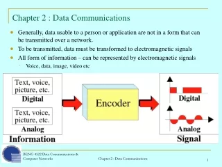
Interfacing • Data processing devices (or data terminal equipment, DTE) do not (usually) include data transmission facilities • Need an interface called data circuit terminating equipment (DCE) • e.g. modem, NIC • DCE transmits bits on medium • DCE communicates data and control info with DTE • Done over interchange circuits • Clear interface standards required
Characteristics of Interface • Mechanical • Connection plugs • Electrical • Voltage, timing, encoding • Functional • Data, control, timing, grounding • Procedural • Sequence of events
V.24/EIA-232-F • ITU-T v.24 • Only specifies functional and procedural • References other standards for electrical and mechanical • EIA-232-F (USA) • RS-232 • Mechanical ISO 2110 • Electrical v.28 • Functional v.24 • Procedural v.24
Electrical Specification • Digital signals • Values interpreted as data or control, depending on circuit • More than -3v is binary 1, more than +3v is binary 0 (NRZ-L) • Signal rate < 20kbps • Distance <15m • For control, more than-3v is off, +3v is on
Functional Specification • (See table in Stallings chapter 6)
Procedural Specification • E.g. Asynchronous private line modem • When turned on and ready, modem (DCE) asserts DCE ready • When DTE ready to send data, it asserts Request to Send • Also inhibits receive mode in half duplex • Modem responds when ready by asserting Clear to send • DTE sends data • When data arrives, local modem asserts Receive Line Signal Detector and delivers data
ISDN Physical Interface • Connection between terminal equipment (c.f. DTE) and network terminating equipment (c.f. DCE) • ISO 8877 • Cables terminate in matching connectors with 8 contacts • Transmit/receive carry both data and control
ISDN Electrical Specification • Balanced transmission • Carried on two lines, e.g. twisted pair • Signals as currents down one conductor and up the other • Differential signaling • Value depends on direction of voltage • Tolerates more noise and generates less • (Unbalanced, e.g. RS-232 uses single signal line and ground) • Data encoding depends on data rate • Basic rate 192kbps uses pseudoternary • Primary rate uses alternative mark inversion (AMI) and B8ZS or HDB3
Foreground Reading • Stallings chapter 6 • Web pages from ITU-T on v. specification • Web pages on ISDN