Download
1 / 6
60 likes | 65 Vues
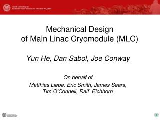
This document presents the layout and design of sensors and instrumentation for the cryomodule in MLC, including cavity, helium vessel, input coupler, and HOM load. Various sensors and controls are discussed. Additional sensor layout for the prototype HOM load cavity is also included.

E N D
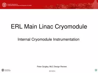
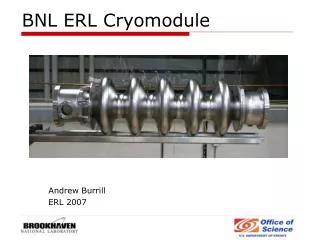
ERL Main Linac Cryomodule Internal Cryomodule Instrumentation Peter Quigley, MLC Design Review
MLC Basic Thermal Map Input Couplers and 80K Shield not shown Support Post HGRP BPM 2K 2-Phase Line HOM Load Cavity Helium Vessel SC Magnet Gate Valve Gate Valve 300K ≤ 2K Peter Quigley, MLC Design Review
Cavity, Helium Vessel, Input Coupler, HOM LoadUnit Sensor Layout HOM Load Cavity Helium Vessel Adjacent Cavity /Coupler CERNOX 1050-SD CLTS HOM Load PT1000 Input Coupler 5K Intercept: Gas Input Cavity Field Probe Port (2) 40K Flange: Gas Input Input Coupler 300K Input Coupler Cooling Gas Input/Output ≤ 2K Peter Quigley, MLC Design Review
Sensor Layout For Cryogenics Piping * CERNOX 1050-SD CLTS PT1000 5K forward 5K local 40K delivery 80K return 6.5K return HGRP 40K forward * 2K 2-Phase Line 40K local *Use of a pressure sensor for flow detection is being considered. 300K Pressure Sensor ≤ 2K Peter Quigley, MLC Design Review
General Instrumentation Information • CERNOX 1050-SD RTD (300K to 1.6K). • CLTS (Cryogenic Linear Temperature Sensor) (300K to 4K). • PT1000 RTD (450K to 40K). • Liquid Helium Level Sensor: 2K type, cold feedthrough. • SC Quad: Lead wire feedthrough LHC type or similar. • Piezo sense and actuator: Noliac, tested in HTC-I,II, and III. • Tuner Motor: Cold, tested in HTC-I,II, and III. • Heaters: • One heater per helium vessel mounted on 2K 2Phase Line. • Two heaters per HOM load, 200W each. • Vacuum Monitoring and Control: Open for discussion. • RF cable: Semi-rigid or Flexible coax. Peter Quigley, MLC Design Review
Cavity, Helium Vessel, Input Coupler, HOM LoadAdditional Sensor Layout For Prototype HOM Load Cavity Helium Vessel Adjacent Cavity /Coupler CERNOX 1050-SD CLTS HOM Load PT1000 Input Coupler 5K Intercept: Gas Input Cavity Field Probe Port (2) 40K Flange: Gas Input Input Coupler 300K Input Coupler Cooling Gas Input/Output ≤ 2K Peter Quigley, MLC Design Review