Download
1 / 21
290 likes | 807 Vues
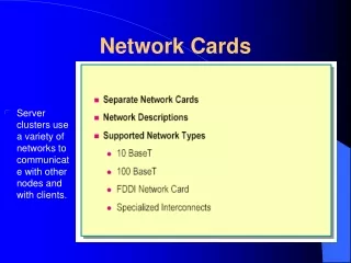
Network Interface Cards. Types. RJ45. LC. BNC. Fiber optic. Wired netcard. Coaxial. Dongles. History of NIC.

E N D
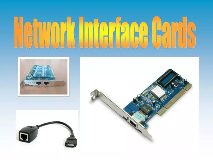
Types RJ45 LC BNC Fiber optic Wired netcard Coaxial Dongles
History of NIC In 1973 Robert Metcalfe needed something that was fast, could connect hundreds of computers, and span a whole building. To solve this problem, Metcalfe developed a rudimentary form of LAN and dubbed it Ethernet. The original Ethernet sent roughly a paragraph of data over thick coaxial cable and could handle a distance of one kilometer.
History of NIC In 1975 Xerox filed a patent listing Metcalf, David Boggs, Chuck Thacker and Butler Lampson as inventors. In 1976 Metcalf wrote a seminal paper that stated the transfer rate was 3 Mbits/second. Metcalf left Xerox in 79 to start the company 3com.
History of NIC In 1981, 3COM built the first 10 Mbits/sec Ethernet adapter. In mid 1980s, Tim Rock, Richard Bennett, Pat Thaler, and others develop StarLAN, the basis for 1BASE5 ethernet In late 1980s the twisted pair design started to replace the coaxial cables.
How the NIC transfers data • The app you are using generates the data you would like to send to another computer. • Your NIC accepts the data from your motherboard and transfers it to a small buffer on the card. • The NIC adds its address (set by the manufacturer) plus the destination address and the type of data to the buffer. • Your NIC calculates the checksum, or CRC, for the data in the buffer.
How the NIC transfers data • The information is arranged into a frame. • The NIC “listens” to the network for other transmissions. If a transmission is heard, it will wait until the transmission is complete. • The NIC begins to serially transmit the frame over the network. • The receiving NIC calculates the checksum for the received frame, then compares it to the checksum it received. • If there are no errors, the receiving station acknowledges the received data.
Translated into 5 steps • The network application retrieves the data being sent. • The NIC puts the address of the other computer onto the data. • The NIC calculates for errors. • The data is arranged into a packet and sent over the network. • The receiving card checks for errors, if there are none, it acknowledges the data.
Transportation The Network interface cards use differing amounts of voltage to transport the 1s and 0s of binary across the cable. For fiber optic cable, different wavelengths of light are passed along.
Application (Layer 7) This layer supports application and end-user processes. Presentation (Layer 6) Session (Layer 5) Transport (Layer 4) Network(Layer 3) Data Link(Layer 2) Physical (Layer 1) This layer translates the data so it can be sent along the network. It is sometimes called the syntax layer. This layer establishes, manages and terminates connections between applications. The session layer sets up, coordinates, and terminates connections at each end. It deals with session and connection coordination. This layer provides transparent transfer of data between end systems, or hosts, and is responsible for end-to-end error recovery and flow control. It ensures complete data transfer. This layer provides routing technologies, creating paths, known as virtual circuits, for transmitting data from computer to computer. Routing and forwarding are functions of this layer, as well as addressing, internetworking, error handling, congestion control and packet sequencing. At this layer, data packets are encoded and decoded into bits. The data link layer is divided into two sub layers: The Media Access Control (MAC) layer and the Logical Link Control (LLC) layer. The MAC layer controls how a computer on the network gains access to the data and permission to transmit it. The LLC layer controls frame synchronization, flow control and error checking. This layer conveys the bit stream - electrical impulse, light or radio signal -- through the network at the electrical and mechanical level. It provides the hardware means of sending and receiving data on a carrier, including defining cables, cards and physical aspects. Fast Ethernet, RS232, and ATM are protocols with physical layer components.
Token Ring Process • Phase 0 (Lobe Check) —The station checks to ensure it can receive these frames without error. • Phase 1 (Physical Insertion) — A station then sends a 5 volt signal to the MSAU to open the relay. • Phase 2 (Address Verification) — A station then transmits MAC frames with its own MAC address in the destination address field of a token ring frame. When the frame returns and if the address copied , the station must participate in the periodic (every 7 seconds) ring poll process. This is where stations identify themselves on the network as part of the MAC management functions. • Phase 3 (Participation in ring poll) — A station learns the address of its Nearest Active Upstream Neighbor (NAUN) and makes its address known to its nearest downstream neighbor, leading to the creation of the ring map. Station waits until it receives an AMP or SMP frame with the ARI and FCI bits set to 0. When it does, the station flips both bits (ARI and FCI) to 1, if enough resources are available, and queues an SMP frame for transmission. If no such frames are received within 18 seconds, then the station reports a failure to open and de-inserts from the ring. If the station successfully participates in a ring poll, it proceeds into the final phase of insertion, request initialization. • Phase 4 (Request Initialization) — Finally a station sends out a special request to a parameter server to obtain configuration information. This frame is sent to a special functional address, typically a token ring bridge, which may hold timer and ring number information with which to tell the new station abort
How the procedure works. Simpler than a token ring, the procedure for coaxial is as following: • Main procedure, it states and asks • Asks: is the frame ready for transmission. • Is medium idle? If not, wait until it becomes ready and wait the interframe period • Starts transmitting. • Asks: did a collision occur? If so, it goes to collision detected procedure. • Resets retransmission counters and end frame transmission. • If a collision is detected it: • Continues the transmission until minimum packet time is reached to ensure that all receivers detect the collision. • Counts how many times it retransmitted • Asks: was the maximum number of transmission attempts reached? If so, abort transmission. • Calculates and wait random back off period based on number of collision • Re-enters main procedure at stage 1.
How long the card waits between retransmission The card counts how many collisions occurred. Then, back-off algorithms determine when the colliding stations retransmit. N = number of collisions The card can wait up to 16 collisions, anything higher and it quits. Slot Time: Twice the time it takes for an electronic pulse to travel the length of the maximum theoretical distance between two nodes.
The Frames A runt frame is a packet smaller than the 64 bytes. This usually occurs because of a collision or an error.
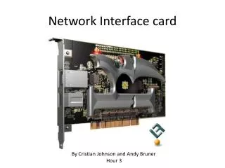
Differences in the cards • The major difference between the cards are the way the data is converted to transmit over the network. Each type of network has its own type of transceiver (transmitter + receiver). 10baseT networks have a specialized transceiver that translates the data into 10baseT Ethernet standards, then transmits it. It also receives information from the network and translates it back into a form the NIC card can use.
Differences in the cards (continued) • 10base2 Ethernet networks have almost the same NIC except for the transceiver. Some NICs have two transceivers, normally 10baseT and 10base2. These dual type cards are known as combo NICs.
Major Manufacturers • ZTE • Cisco Systems • Hewlett-Packard • 3Com • Linksys • Belkin • Dlink
FDDI • Fiber Distributed Data Interface Can support thousands of users Uses duel token ring setup Due to their speed, cost and ubiquity, fast Ethernet and (since 1998) Gigabit Ethernet have largely made FDDI redundant. Needs two Token ring supportable cards or two jacks on the card.
Price • The cards can range in price from $10 to $800. Most cards are actually around $20.
References • Webopedia.com • Howstuffworks.com • http://everything2.com/title/How+Network+Adapters+Work • Wikipedia.com • Bestbuy.com http://www.eflnet.com/networking/acrolist.php?firstletter=F