Download
1 / 33
370 likes | 656 Vues
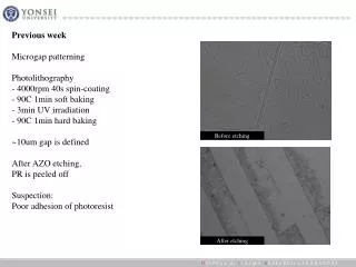
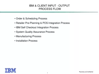
IBM Spin Coating Process. Greg Burtt Greg Hewitt Dave Valente Contact Engineer: Kevin Remillard Faculty Mentor: Jeff Marshall. Photo Resist. Process Setup:. Chuck. Silicon Wafer. Nozzle. Vacuum. 200. Problem Statement.

E N D
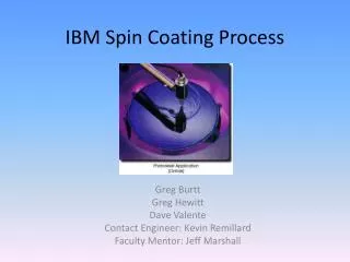
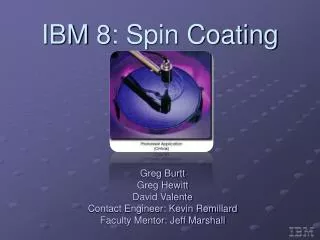
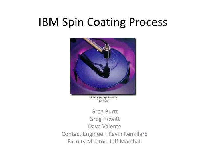
IBM Spin Coating Process Greg Burtt Greg Hewitt Dave Valente Contact Engineer: Kevin Remillard Faculty Mentor: Jeff Marshall
PhotoResist Process Setup: Chuck Silicon Wafer Nozzle Vacuum 200
Problem Statement • During the spin coating process, defects sometimes appear on the wafer. • Damage to the bowl from handling and cleaning have also been spotted as a cause of the defects. • A cleaning process must be run twice a day to remove built up resist from the “bowl set” (the 3-part set of plastic pieces that houses the silicon wafer being coated and collects the excess applied chemicals) in order to reduce the probability of defects. • Resist build up and defects from handling are understood to disrupt airflow • This cleaning process involves the use of a cleaning disk and a solvent to attempt to remove as much resist as possible from the bowl, but it is incapable of removing all of the build-up. • Consequently, the bowl set must be removed every two weeks and trucked to a company that cleans them. This is a very costly process for IBM for a few reasons. • There is a lot of down-time involved in removing and replacing the bowls, this is time translates directly to lost money because of decreased productivity. • They must also pay to have the bowls trucked to a facility and to have them cleaned there. • Some bowl sets come back with damage and need to be replaced.
X-Section of Bowl Setup:Original Disk Resist Buildup Target Cleaning Disk Chuck Fluid Exit Hole Nozzle Vacuum 200
Cleaning Process • Cleaning Recipe • 2500RPM for 5 seconds • 2500RPM for 60 seconds with both backside rinse nozzles on • 100RPM for 60 seconds with both backside rinse nozzles on • 50RPM for 60 seconds with both backside rinse nozzles on • 2000RPM for 10 seconds • Total flow rate from both nozzles is 50mL/min
Defect Description • Wafer defects are thought to be caused by the loss of proper air flow through the bowl setup. • Very small particles (“ball bearings”) of resist become suspended in the air during the normal application process, the flow ideally carries all these particles away from the wafer surface into a drain. • In some cases, the flow becomes disrupted allowing these particles to return from the air to the wafer surface. Alternatively, the flow picks up new ball bearings from the sides of the bowl and deposits them on the wafer surface. Either instance results in a defect on the wafer. • IBM believes, and we will assume their conclusion is correct, that in an otherwise undamaged bowl, these defects are primarily caused by a build-up of dried resist on the bowl surfaces.
Excursion Monitor Testing Clockwise from top right: Solvent droplet defect Ball-bearing defect (photoresist) XMO (excursion monitor wafer) XMO scan results (the dot is the location of the found defect) The photographs on top are from an excursion monitor ran at IBM during testing. .75µm lines are etched on a wafer and it is then developed and scanned for defects. Vertical lines are spaced .75µm apart
Constraints • Process chemicals cannot be changed • Wafer spin speed is variable, so a solution must accommodate any angular velocity up to a maximum of several thousand RPMs • IBM prefers that the bowl geometry remain unchanged • Exhaustive testing would have to result • Cost to IBM can not exceed savings • This includes the cost associated with disk manufacture and cleaning as well as equipment down-time for cleaning and bowl changes • Cleaning disk overall dimensions cannot change.
Possible Solutions Considered • Redesign airflow through bowl set • Minimize defects no matter how dirty the bowl becomes • Problem: Coating wafers uniformly requires strict airflow parameters • Modify cleaning disk and cleaning recipe • Minimize build up of resist in bowl with minimal change to existing system • Problem: Altering current process could cause defects due to airborne solvent particles • Modify bowl coating • NxEdge offers bowl coating that claims to minimize resist buildup.
Project Goal • By April 30th, 2008 a final disk prototype, cleaning recipe, and bowl coating decision will be made that will reduce the frequency with which the bowls are removed for cleaning from once every two weeks to at most once every four weeks.
Bowl Coating • Initially, the idea of applying a coating to the bowl parts that would minimize the buildup of photoresist • NxEdge sent IBM a presentation for just such a product shortly after • A sample bowl set was coated for our testing purposes • Unfortunately two major complications kept tests of this bowl from proceeding • UVM would not allow any photoresist or solvent on the premises • Time constraints would not allow for long-term testing at IBM • Cost is $575 per set of bowls, coating is expected to last about one year • IBM needs 150 bowls coated for a total cost of $86260 • Trucking and cleaning costs $170000 per year, so the cost is not completely unreasonable
Cleaning Disk Original Designs Eventually discarded due to complex manufacturing and the cost associated.
Design Road Map • 1st Semester: • September 12th 2007: Decision to focus upon the cleaning disk as a design project. • September 26th 2007: Solidworks drawings start to take a real form. Difficulty of manufacture of things like nozzle passages begin to be realized. • October 9th 2007: Two cleaning disk models have been created in Solidworks. Two models were ranked using a Pugh chart, a single design remains. • November 15th 2007: The disk comes back into focus after a month of thinking about test stand design. Ease of manufacture is becoming a very important factor, new ideas are tossed around for next semesters testing. • December 6th 2007: It’s been decided by this point that we would not create a new disk, but modify IBM’s existing disk with several different hole patterns. Many different ideas were drawn up to be tested for the following semester. • December 14th 2007: At a second visit to IBM, a close examination of the cleaning process reveals a strip of resist above the bowl knee, untouched by solvent projected by the cleaning disk. The scope of the project narrows to determine ways to effectively project solvent to this region, thereby removing the resist causing ball-bearing defects. • 2nd Semester: • February 11th: Construction of the test stand begins. Parts being ordered as stand built. Still waiting on stepper motor. • February 28th 2008: Preliminary testing of Prototype 1 at IBM. Prototype does not remove target strip of resist. • March 5th 2008: Test stand problems of balance at high RPM prevent much from developing. • March 18th 2008: Shaft balancing problems continue. Modifications made to test stand to fix the balancing issues. • April 9th 2008: Test stand completed, the original disk is completely classified. • April 11th 2008: The first testing modification made, holes in the top of the disk is tested and fails. • April 12th 2008: All initial designs do not get the fluid where we want. Breakthrough test of disk without its spray skirt jumpstarts final design idea. • April 14th 2008: Prototype made with wide grooves for fluid to flow up and out of the disk at a higher angle does the trick. Testing at IBM to follow the very next day. • April 23nd 2008: Final clean prototype made. • April 24th 2008: Testing of final prototype at IBM is successful.
Test Stand Set-Up and Calibration Preliminary Airflow Calibration: Between 650 and 700 linear feet per minute
Backside Rinse Nozzles Backside Rinse Volumetric Flow Calibration: 100mL/minute
The velocity of the fluid exiting the .95mm holes on the original disk during the 2500 RPM cycle was calculated to be 29cm/s. This corresponded to only .1mm in fluid height, a number that was questioned until initial tests confirmed the calculations were correct. When the primary concept was to add additional holes aiming upward, the velocity out the existing holes and one additional hole was plotted as a function of the diameter of the new hole. Fluid Exit Velocity Calculations
Resist Buildup Target X-Section of Bowl Setup:Original Disk Cleaning Disk Chuck Fluid Exit Hole Nozzle Vacuum 200
Resist Buildup Target X-Section of Bowl Setup:Final Prototype Cleaning Disk Chuck Fluid Exit Hole Nozzle Vacuum 200
Flow From the New Slots The flow out of the slots on the modified disk is more of a spray than the stream that is observed to come from the original holes
Photoresist/Solvent Tests At IBM Photoresist was applied to the top bowl
Post-Cleaning Results Original Disk Prototype Disk After the cleaning process was run, the top bowl was inspected. The prototype cleans above the knee, where the original disk fails to reach.
Airborne Particle Detection A particle detector was used during the last round of testing at IBM to measure the amount of solvent dispersed into the air inside the photolithography machine. Three minute long cycles were used, sampling the air at a rate of .9cfm. IBM had never done this test with their existing cleaning process, but it was a major concern that if the new cleaning disk put more solvent particles into the air, it could cause more defects. To everyone’s surprise, the cleaning process created no particles between .1 and 1µm. The prototype cleaning disk created minimal amounts of particles on the first three runs, and then dropped to zero. Presumably, the first particles were left over from machining and transporting the prototype. Particle detection results for the first cleaning disk test.
Excursion Monitor Testing and Results Results: Six wafers tested. Only nine defects were found. This is well below the threshold value. 1.) Run cleaning disk 2.) Process 3 wafers 3.) Inspect wafers for defects
Final IBM Test Data • The final design passes three criterion • The prototype removes the target resist • No increase in atmospheric solvent particles compared to the original disk • No increase in wafer defects compared to the original disk Success!
Overall Cost of Project: $1,815.71 Return on Investment: $85,500 saved in trucking and cleaning costs per year Production capacity increased by 29,000 wafers per year Summary of Finances
Closing Remarks • IBM will be doing some long term tests of both the prototype and the bowl coating. • Special thanks to Kevin Remillard, Jeff Marshall, Rick Phelps, Anthony Fouche, Kurt Anthony and Floyd Vilmont.