Download
1 / 32
320 likes | 471 Vues
Solar-B EIS Engineering Meeting at MSSL July 27 - 29, 1999 H. Hara (NAOJ). EIS /Solar-B. Documents for Subsystem Design. Document Name Date Language Thermal Design Standard for Solar-B (DRAFT) Feb 12,1999 J

E N D
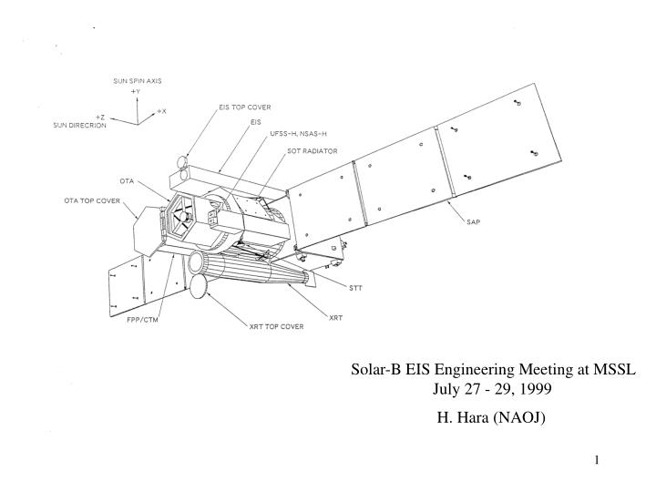
Solar-B EIS Engineering Meeting at MSSL July 27 - 29, 1999 H. Hara (NAOJ)
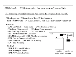
EIS/Solar-B Documents for Subsystem Design Document NameDate Language Thermal Design Standard for Solar-B (DRAFT) Feb 12,1999 J Requirements for Structural Mathematical Models Mar 8,1999 E Mechanical Design Standard (DRAFT) Mar 8, 1999 J+E Environmental Conditions for Solar-B (DRAFT) Mar 8, 1999 J+E Contamination Control Program Plan for Solar-B (DRAFT) Mar 8, 1999 E Solar-B Electrical Design Standard (DRAFT) Apr 24,1999 J (DRAFT) July 27,1999 E Solar-B/Telescope Thermal Interface Condition (DRAFT) June 30, 1999 J+E Requirements for Interface Thermal Math Model of Solar-B Telescope (DRAFT) June 30, 1999 J+E Telemetry & Command Design Standard (DRAFT) not yet made
summary report of satellite design meeting on June 30, 1999 EIS/Solar-B Requests from System side to EIS 1. Position of Mounting I/F points. There is inconsistent with the I/F legs. Change the drawing to meet the I/F points before making structure math model. 2. Electrical relationship among ICU, MHC, and FPA. How these are connected by electrical lines ? 3. Ranges of temperature is too narrow. Widen the ranges (relatively urgent). 4. Show disturbance torque of each moving component (urgent issue). 5. 32 W solar power is input in EIS at entrance filter. Is this OK ? How is this energy to be treated ? 6. Number and location of survival heaters when EIS primary power is off. Temperatures for switch-on and switch-off controls should be reported. The survival heaters are controlled by HCE. At present three survival heaters are allocated to EIS by the request of Japanese side, though the usage is uncertain. This issue must be reported to the system side by July 15.
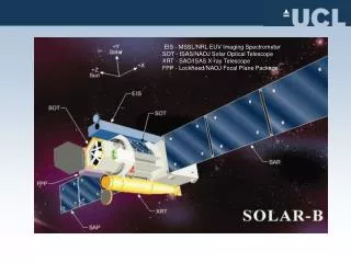
summary report of satellite design meeting on June 30, 1999 EIS/Solar-B Solar-B system issues Telemetry & Command system: ASTRO-F system was adopted. Summary of electrical interface related to EIS was shown (see Fig. 1 ). Satellite structure almost meet the size of fairing envelope. (exception: XRT & EIS. In case of EIS, interface points should be shifted to -Z direction.) ICU is put at low part of +Y side panel of bus structure (Fig.2). Weight of EIS: EIS-STR 50.3 kg, EIS-ICU 6.0 kg, EIS-HAR 4.0 kg. Margin of 9 kg is managed by system side in a different level of system issue. Power: ICU: Wmax = 60 W, Imax = 2.3 A Heater power of 10 W is tentatively allocated to EIS because of no input. Thermal analysis of optical bench + mounting legs + bus structure was almost finished. Change of optical axes of SOT, XRT, and EIS is only 0.2-0.3 arcsec during the sun- synchronous orbit in the worst case. The infinite rigid body for telescopes is assumed in this analysis.
summary report of satellite design meeting on June 30, 1999 EIS/Solar-B Solar-B system issues Harness: If there is an electrical harness whose length should be less than 4 m by some reason, we must report it to the system side. Power savings: Even in the case of sun-synchronous orbit, satellite night comes in some period. System asked all telescope teams if the power saving can be done during the night period or not for power saving. Bus voltage for SOT, XRT, and EIS is 28 +/- (A) V. (A) will be less than 2. Structure math model: The schedule of structure analysis was updated (see Fig. 3). Thermal math model: The schedule of thermal analysis was updated (see Fig. 4).
summary report of satellite design meeting on June 30, 1999 EIS/Solar-B Electrical Interface of EIS bus structure EIS-STR HCE survival heater #1- #3 TCI-B EIS-ICU DIST T-sensor #8 - #9 MDP T-sensor #1 - #7 DHU PIM DC/DC signal line HKU primary power on/off CMD+TLM 28V primary power line Fig. 1 secondary power line
summary report of satellite design meeting on June 30, 1999 EIS/Solar-B Location of EIS-ICU in Bus Structure EIS-ICU Fig. 2
summary report of satellite design meeting on June 30, 1999 EIS/Solar-B Schedule of Structure Analysis July Aug. Sep Oct. bus subsystem math model math model SOT, XRT, EIS System side Coupled Load Analysis combine math models to satellite math model Fig. 3
System Analysis of thermal distortion Analysis of Bus structure & Optical Bench for deriving temperature distribution temperature of I/F points temperature of boundary System thermal analysis Thermal design standard Thermal Interface Requirements to the telescope thermal math model Thermal I/F condition Thermal model design Instruction Update Thermal I/F condition Thermal model design Instruction Thermal design Information I/F Thermal Math Model Themal design analysis of EIS Detail Themal design analysis of EIS Preliminary Telescope Team (EIS) summary report of satellite design meeting on June 30, 1999 EIS/Solar-B Schedule of Thermal Analysis Flowchart during Phase A study Phase A B Time End of June End of Oct. End of Nov. Mar. 8 Beg. of July End of May End of July End of Dec. I/F Thermal Math Model Update Phase A Thermal Design Analysis Fig. 4
EIS/Solar-B MDP development schedule Specifications of MDP shall be fixed by the following dates: hardware related issues: August 31, 1999 software related issues: November 30, 1999 Purpose of PM tests (Feb 1 - Mar 31, 2001) Interface with SOT, XRT, EIS, DHU, TCI-B, HCE, DIST – establishment of hardware interface – establishment of software protocol – establishment of exposure sequence Confirmation of main processing functions – confirmation of processing command/telemetry – confirmation of processing science data including compression
EIS/Solar-B PM test plan of MDP MDP I/F with mission instrument observation table parameter table command receipt satellite bus I/F satellite bus SOT command transmission XRT management satellite time EIS receive status data telemetry format receive image data bit comp. image comp. create secondary power primary power I/F
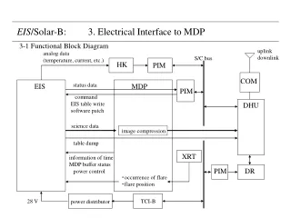
image compression XRT EIS/Solar-B Electrical Interface with MDP S/C bus uplink downlink analog data (temperature) HKU PIM COM status data EIS MDP PIM command EIS table write software patch DHU science data table dump information of time MDP buffer status power control ・occurrence of flare ・flare position PIM DR 28 V DIST (power distributor) TCI-B temp. for HC HCE (heater control) command status
HS-26C31 HS-26C32 EIS/Solar-B Interface lines EIS MDP DATA CLOCK ENABLE All electrical interface lines between EIS and MDP are digital interface lines. Normal RS-422 1 MHz MDP BUFFER STATUS differential RS-422 line interface COMMAND CLOCK ENABLE low-power RS-422 64 kHz ‘MDP Buffer Status line is used 1: for safe exchange of ‘input buffer’ in MDP. 2: when post compression buffers become almost full. status data interface DATA CLOCK ENABLE low-power RS-422 64 kHz hardware command I/F for secondary power on/off hardware status I/F for secondary power hardware status I/F for others if required
bit comp. EIS/Solar-B Flow of image data processing in MDP Input Buffer buffer A SOT-A buffer B SOT-B Post Compression Buffer buffer A XRT-A output buffer image compression buffer B XRT-B DHU DPCM EIS-A 8Mbyes JPEG EIS-B 8Mbyes EIS can use functions of bit compression & image compression in MDP.
EIS/Solar-B Data lines ・Data line: normal differential RS-422 line, 1Mbps ・ Science data (spectrum or image) ・ Status data ( ~1 sec interval; Report of shutter & scan mirror motions will be required.) ・ Dump data of EIS observation table ・ Dump data of EIS compression table MDP knows kind of data by looking at the header part after the data are transferred. 12 bits data flow in this data line. maximum transfer speed: 1 Mbps (TBD) EIS MDP ・EIS Input Buffer in MDP: 1. double buffer system 2. buffer size: 8 Mbytes/buffer ・Concept of Data Format: fixed-length header + variable-length data maximum image size in a single packet = 256 kpixel science data: header + 12 bits CCD image data The number of pixels in the image data is a multiple of 8. Is this OK ? other data : header + 12 bit data (Upper 4 bits are all 0. Is this OK ?) EIS can send data to MDP at any time when a status of MDP buffer status line is READY.
status data interface DATA CLOCK ENABLE low-power RS-422 64 kHz HS-26C31 HS-26C32 EIS/Solar-B Recommended status line interface Data format DATA1 DATA2 DATA3 DATA4 DATA N Data format is consistent with requirement of PIM. 8 bits 8 bits 8 bits 8bits 8bits REQUIREMENTS Request of sending status data is informed from MDP via command line, and EIS shall send status data to MDP within 0.5 sec. status request command from MDP via command I/F < 0.5 sec status data to MDP via status I/F
EIS/Solar-B Data Compression MDP EIS image comp. post comp. buffer input buffer bit comp. 14 bit →12 bit bit compression (selectable) (selectable) DHU CCD buffer DPCM JPEG header DR 2.4 Gbits 1 Mbps line 12 bits data 2 Mbps (TBD) line for SOT, XRT & EIS Header includes information of data compression in MDP. for EIS EIS can use 2 Mbps line nominally for 0.5 s every 6 seconds. max. 167 kbps, but DR for EIS will become full in a short time. Capacity of DR will be ~3 Gbits, but only downlink 2.4 Gbits during the KSC/DSN contacts.
EIS/Solar-B Command Lines Command line: low-power differential RS-422 line, 64 kbps MDP contractors would like to know: 1. list of commands required for EIS operation 2. how ICU reads commands from MDP (Please explain it.) 3. response time for a command 4. size of buffer ? 5. whether there is some restriction for the data format or not. Command answer back: receipt of command put the command data into status data for confirmation.
HS-26C31 HS-26C32 MDP EIS 100Ω±10% 4.7KΩ±10% + 100Ω±10% 4.7KΩ±10% - driver receiver No resistance 1 line/component Driver device:HS-26C31 Receiver device:HS-26C32 EIS/Solar-B Hardware command interface Purpose: Irrespective of MDP CPU status, the secondary power on/off commands and others are sent via hardware command interface. MDP a b c EIS STROBE STROBE DATA4 DATA3 DATA2 DATA1 DATA0 DATA minimum interval of command transmission command command t 31.25 msec (min) reference: Solar-B Electrical Design Standards §8-(8)
VDD MDP EIS R1 R2 U1 C1 Circuit type: TB-E-R Circuit type: TB-E-T VDD : +5V ±TBD V U1 : CMOS 4049/4050 C1 : 220pF ± TBD % R1 : 27KΩ± TBD % R2 : 10KΩ± TBD % + - EIS/Solar-B Hardware status interface for secondary power Purpose: ON/OFF status of EIS secondary power relay is periodically monitored by a hardware logic circuits. MDP EIS status 0 status 1 status N or MDP +5V 2.5KΩ EIS MUX Logic 1:open (more than 1MΩ) Logic 0:close (10Ω) Input impedance:more than 1MΩ reference: Solar-B Electrical Design Standards §8-(6) or (7)
HS-26C31 HS-26C32 MDP EIS 100Ω±10% 4.7KΩ±10% + 100Ω±10% 4.7KΩ±10% - driver receiver No resistance 1 line/component Driver device:HS-26C31 Receiver device:HS-26C32 EIS/Solar-B Hardware status interface for important bi-level status Purpose: Important bi-level status data are periodically monitored by a hardware logic circuit. MDP EIS Status N+1 Status N+2 Status N+M N: Number of “secondary power status” M: Number of “H/W status” reference: Solar-B Electrical Design Standards §8-(8)
EIS/Solar-B Counter-plan for Errors ・When some error happens in EIS-CPU due to SEU, does EIS side request anything to MDP ? or does EIS side deal with the error by itself ? ・When some error happens in MDP due to SEU, does EIS side request anything to MDP backup system for safety ? or does EIS side deal with the error by itself ? MDP realizes stop of EIS CPU by the following procedure. • MDP sends a status request command and waits for 0.5 sec. • When the same procedure is done three times in a condition that status data do not come to MDP, MDP judges that EIS CPU is down. <This is effective only when the status line is independent of science data line.>
5 4 3 2 1 E 4 D C B 3 2 1 A EIS/Solar-B Management Plan of Time clock line in command line EIS MDP DHU clock generator clock counter clock counter ・obtaining count c1 at a start of exposure ・obtaining count c2 at a start of data transfer. PIM time ・obtaining c3 at start of data receipt ・obtaining c4 at start of receiving PIM time. PIM These counts are added to image data. These counts are added to compressed image data. A: CCSDS packet header B: count c3 at start of receiving image data C: PIM time D: count c4 at start of receiving PIM time E: compressed image data 1: header 2: count c1 at start of exposure 3: count c2 at start of data transfer 4: image parameter 5:image data data line for image data In case of data except for science data, EIS only put counter value at start of data transfer.
EIS/Solar-B Flare Detection The following is a baseline of flare detection. ・Detection of flares is done by XRT. ・8×8 on-chip summation image covering the whole XRT field of view will be used for flare patrol. ・The flare patrol image will be taken every ~30 sec (TBD). ・Information on flare detection is sent to EIS by MDP. 1. Flare detection 2. Flare location in XRT CCD coordinate; X=0-255, Y=0-255 (TBD) ・Duration of flare mode TBD time flare patrol image flare mode ~30 s Flare! flare observation with EIS time for XRT data analysis (TBD) time for change of EIS FOV
EIS/Solar-B Command to MDP < ASTRO-F type command system (similar to Yohkoh system) > Type Classification Command Types Discrete Command (DC) Block Command (DC+BC+...+ BC) Command Block Type Individual Command Organized Command (OG) Command Grouping Real-time command Time-tagged command Operation Program (OP) Onboard-triggered command Operation Type OP and Onboard-triggered command support only OG to execute.
EIS/Solar-B Command System Block Diagram DHU/DR MDP science data status observation table for SOT observation table for XRT PIM OP/OG command TLM CMD command command command status status status data data data EIS-E SOT FPP-E Real-time command real OG execution OP/OG upload time-tagged command XRT Observation table for EIS ground
EIS/Solar-B Data length of Command Command Block Type Maximum data length (bytes) DC 1 DC+BC+…..+BC real time 1 + 252 OP/OG 1 + 13 time-tagged 1 + 8 DC is used for single task such as ON/OFF, START/STOP and ENA/DIS. BC is used for data transmission such as program load, table upload, and so on. Real-time commands are sent from the ground and are immediately executed. Time-tagged commands are stored in DHU and executed at a specified time in a resolution of about 1 sec. 32 commands can be stored in DHU.
EIS/Solar-B OP & OG OP: Operation Program; a group of time-line commands consisting of OG. 512 (TBD) time-line slots are prepared for OP. Each time line is executed at a time defined by time interval between consecutive two time lines. The unit of time interval is TBD sec. OP is started at a Kagoshima contact pass. OG: OrGanized command; One OG has 16 (TBD) command slots. Discrete command or block command data is included in each slot. 256 (TBD) OG can be stored in DHU. Time interval between two slots in an OG is 62.5 msec. Example of OP: CE #OG Interval 00 0 121 NOP 01 3 32 KSC LOS 02 22 85 DSN AOS …… 129 255 OP STOP Example of OG: 00: 03-DC-11 08: 05-DC-42 01: 09: 05-BC-12 02: 03-DC-23 10: 05-BC-45 03: 11: 05-BC-32 04: 12: 05: 13: 06: 14: 07: 15: 03-DC-44
EIS/Solar-B MTM Test (May 15 - Aug 31, 2001)
EIS/Solar-B Mechanism & Operation Mechanism: purpose frequency direction angle of rotation or shift outside observation: DOR: protect inside from dirty environment once/year ar. Y-axis 180deg/ 10 sec LOK: increase of stiffness once/mission ar. X-axis ~30 deg GRA: focus adjustment once/year ± Z-axis ±0.5 mm/10sec CLM: opening of vacuum enclosure once/mission ar. Y-axis 90 deg/10 sec SLI : focus adjustment once/mission? ± Z-axis ±0.5 mm/10sec change slit/slot once/hour ? ar. X-axis 90 deg/10 sec MIR: change field of view once/day ? ± X-axis ±5arcmin/10sec during observation: MIR: scan for raster observation once/ 1 sec ar. Y-axis 1 arcsec/ 0.5 sec reset to start position once/5-10 min ar. Y-axis 8 arcmin/ 5 sec SHU: adjust exposure duration once/ 1 sec ar. Z-axis ~60 deg/0.1 sec (SLI: change slit/slot once/ hour ar. X-axis 90 deg/10 sec )
EIS/Solar-B scan mirror: [raster step] = 1 arcsec, dt = 0.5 sec T = 4.9e4 • 10-7 • 4.8e-6 •0.5-2 = 9.4e-8 (N m) [motion to home position] = 4 arcmin, dt = 5 sec T = 4.9e4 • 10-7 • 4.8e-6 • 240• 5-2 = 2.3e-7 (N m) 0.5 s t Disturbance Torque (order of estimation) Disturbance torque during a motion: T = d (I )/ dt ~ I (dt)-2 momentum of inertia estimated by CMB unit (g cm2) scan mirror: Iy = 4.89e4 shutter : Iz = 36.7 slit : Ix = 44.3 slit: = 90 deg, dt = 10 sec T = 44.3• 10-7 • 4.8e-6 • 3600 • 90• 10-2 = 1.9e-4 (N m) = 6.9e-8 (N m) 6.9e-6 (N m) for dt = 1 sec shutter: = 30 deg, dt = 0.1 sec T = 36.7 • 10-7 • 4.8e-6 • 3600 • 30• 0.1-2 = 1.9e-4 (N m)
EIS/Solar-B Acceptable Level of Disturbance Torque from handouts distributed in satellite design meeting held on June 30, 1999