Download
1 / 9
100 likes | 214 Vues
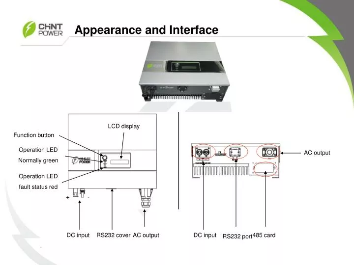
Appearance and Interface. LCD display. Function button. Operation LED Normally green. AC output. Operation LED fault status red. +. -. DC input. RS232 cover. AC output. DC input. 485 card. RS232 port. Appearance and Interface. Positive. Negative. Line. Neutral. Grounding.

E N D
Appearance and Interface LCD display Function button Operation LED Normally green AC output Operation LED fault status red + - DC input RS232 cover AC output DC input 485 card RS232 port
Appearance and Interface Positive Negative Line Neutral Grounding
Appearance and Interface,DC switch This is an isolating switch. Don’t switch on or off with electricity. on Negative Grounding off positive DC output DC Input
Connecting to the grid (AC utility) • 1. Measure grid (utility) voltage and frequency. It should be 230VAC, 50Hz, • and single phase. • 2. Open the breaker or fuse between PV-Inverter and utility. • 3. For CPS SC1.5KTL, SC2.8KTL, SC2KTL, SC4KTL and SC4KTL-O, • connect AC wires as follows: • Insert utility wires through cable gland. Connect wires according to polarities indicated on terminal block. L LINE (red、brown、black), N Neutral (blue) and PE system ground (yellow-green). • Refer to left figure. • To prevent risk of electric shock, ensure the ground wire is properly earthed • before operating the PV-Inverter. Suggested cable width for AC wire This cover is only used on the outdoor system.
Connect to DC Switch 1. Installation environment: either indoor or outdoor, ambient temperature: -20℃-+50℃ 2. The minimum space requirements are shown as left 3. The installation positions can be any one of the three modes shown left. The first mode is recommended. a. Drill four holes with 6mm diameter and not less than 32mm depth on wall or a support as the size (140 × 70mm) shown left. b. Fix the switch to the wall or support with four expansion bolts supplied with the switch according to the method shown left.
Connect to DC Switch 1. Cable fabrication Connectors A supplied with the switch (two male connectors and two female connectors) are crimped with cable B whose conductors have 4.0mm2or 12AWG cross section. Connectors suitable to the equipment to be connected are used at the other end C of the cable. Ground terminals D (2 PCS) supplied with the switch are crimped with a yellow green cable E whose connectors have 4.0mm2 or 12 AWD cross section. 2. Before the switch is connected with the equipment, and place a knob of the switch at "OFF" position. 3. The following diagram shows how the switch is connected with the equipment and grounded. The recommended connection sequence is grounding, connection with the inverter followed by connection with the junction box. 4. Keep the knob of the switch at “off” position until power on the inverter.
Connect to Inverter 1. Make sure the maximum open circuit voltage (VOC) of each PV string is less than 500VDC(or 450VDCfor CPS SC1.5KTL) UNDER ANY CONDITION. We recommend use the solar modules, whose total Umppat STC in the string between 250VDCand 350VDC(200VDCand 320VDCfor CPS SC1.5KTL) with ambient temperature 25°C. 2. Use MC-4 connectors for PV array terminals. 3. Connect the positive and negative terminals from the PV panel to positive (+) terminals and negative (-) terminals on the PV-Inverter. Make sure the polarity is correct!!! Positive connector Negative connector Disconnect the cable connection requires specialized tools
MC4 connector Use small standard crimping tool to fasten it specified tools to disconnect the MC4 connector, this tool included in each inverter’s accessories . Also if there is no the right tool, a small screwdriver can be used instead
Power on Click it ON OFF Click it ON OFF 1:Make sure the maximum open circuit voltage (VOC) of each PV string is less than 500VDC(or 450VDCfor CPS SC1.5KTL) UNDER ANY CONDITION. 2:Make sure the polarity is correct. 3:When the PV panels are connected and their output voltage is greater than 100 VDC but the AC grid is not yet connected, the message on the LCD display produce the following messages in order: “MODEL= CPSSCxxKTL” -> “Waiting” -> “No Utility”. The display repeats “No Utility”and the RED “fault LED” turns on. 4. Close the AC breaker or fuse between PV-Inverter and grid. The normal operating sequence begins. 5. Under normal operating conditions the LCD displays “Watt=xxxx.xW”. That is the power fed to the grid. The green LED turns lights-up.