Download
1 / 29
290 likes | 536 Vues
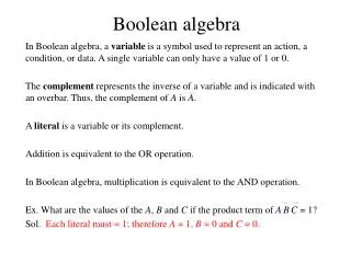
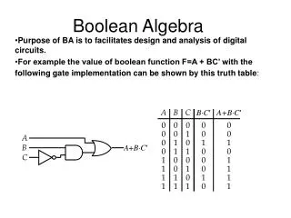
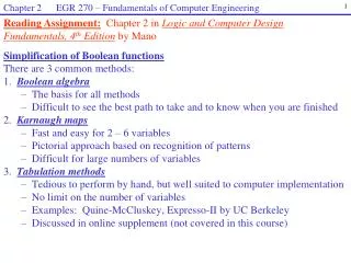
Chapter 2 EGR 270 – Fundamentals of Computer Engineering. 1. Reading Assignment: Chapter 2 in Logic and Computer Design Fundamentals, 4 th Edition by Mano. Simplification of Boolean functions There are 3 common methods: 1. Boolean algebra The basis for all methods

E N D
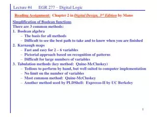
Chapter 2 EGR 270 – Fundamentals of Computer Engineering 1 Reading Assignment:Chapter 2 in Logic and Computer Design Fundamentals, 4th Edition by Mano Simplification of Boolean functions There are 3 common methods: 1. Boolean algebra The basis for all methods Difficult to see the best path to take and to know when you are finished 2. Karnaugh maps Fast and easy for 2 – 6 variables Pictorial approach based on recognition of patterns Difficult for large numbers of variables 3. Tabulation methods Tedious to perform by hand, but well suited to computer implementation No limit on the number of variables Examples: Quine-McCluskey, Expresso-II by UC Berkeley Discussed in online supplement (not covered in this course)
Chapter 2 EGR 270 – Fundamentals of Computer Engineering 2 Karnaugh Maps (K-maps) Essentially a 2D truth table arranged in a table or map so that adjacent cells in the map differ in only one bit position. Each cell in the map corresponds to a minterm. Combining 1’s in the Kmap into groups of 1, 2, 4, 8, etc. can yield a quick minimization of a Boolean function. Kmaps are most commonly used for functions involving 2-6 variables. 2-variable K-maps The K-map has 22 = 4 cells. Example: Use a K-map to minimize the function f(x,y) = x’y + xy’ + xy
Chapter 2 EGR 270 – Fundamentals of Computer Engineering 3 Example: Use a K-map to minimize each function below. 1. yz Group is x’y (x = 0 and y = 1) 00 01 11 10 x 3-variable K-maps The K-map has 23 = 8 cells. 1 0 1 0 0 0 1 1 0 1 “Wraparound” group is xz’ (x = 1 and z = 0) Answer: f(x,y,z) = x’y + xz’
Chapter 2 EGR 270 – Fundamentals of Computer Engineering 4 2. f(x, y, z) = (0, 1, 5, 7) 3. f(x, y, z) = xyz + x’yz + x’y’z’ + y’z 4. f(a, b, c) = ab’ + ac + ab + b
Chapter 2 EGR 270 – Fundamentals of Computer Engineering 5 Example: Use a K-map to minimize each function below. 4-variable K-maps The K-map has 24 = 16 cells.
Chapter 2 EGR 270 – Fundamentals of Computer Engineering 6 Group size vs. number of literals: Note how the number of literals in a term is reduced by one each time the size of grouping is doubled. For the 4-variable K-map: Example: Use a K-map to minimize each function below. 1. f(A, B, C, D) = A’B’C’ + A’CD + B’CD’ + ABD + AB’D + AB’C’D’ 2. f(A, B, C, D) = B’D’ + C’D + BD’ + A’D + BC
Chapter 2 EGR 270 – Fundamentals of Computer Engineering 7 Prime Implicants Prime Implicant – a product term which cannot be combined with other terms to yield a term with fewer literals. Hint: A prime implicant corresponds to a maximal grouping in a Kmap. Essential Prime Implicant – a prime implicant that covers at least one minterm of the function that is not covered by any other prime implicant. A good way to approach finding minimal expressions in Karnaugh maps is to find essential prime implicants first. Once those groups have been drawn on the map, it is easier to see what other groupings would most efficiently cover the rest of the minterms. In general, a function can be expressed as: F = sum of essential prime implicants + (some combination of non-essential prime implicants) Example: Identify all prime implicants and all essential prime implicants in f(A, B, C, D) = (0, 1, 3, 4, 5, 7, 11, 15)
Chapter 2 EGR 270 – Fundamentals of Computer Engineering 8 Example: Use a K-map to minimize each function below. Identify the essential prime implicants in each problem.
Chapter 2 EGR 270 – Fundamentals of Computer Engineering 9 5-variable K-maps The K-map has 25 = 32 cells. Note odd arrangement of the variables ABCDE. This arrangement results in the left half of the K-map having the same minterm ordering as a 4-variable map. Note that groups combine as if the left map was over the top of the right map (like 3D chess). These two groups combine to form B’DE’ ADE 000 001 011 010 1 00 101 111 110 BC m0 m3 m2 m16 m17 m19 m18 m1 00 m4 m7 m6 m20 m21 m23 m22 m5 01 m12 m13 m15 m14 m28 m29 m31 m30 11 m8 m9 m11 m10 m24 m25 m27 m26 10 These two groups do NOT combine!
Chapter 2 EGR 270 – Fundamentals of Computer Engineering 10 5-variable K-maps (alternate minterm ordering) Shown below is an alternate arrangement for the variables A, B, C, D and E. Note that changing the arrangement of the variables changes the ordering of the minterms. CDE 000 001 011 010 1 00 101 111 110 AB m0 m1 m3 m2 m4 m5 m7 m6 00 m8 m9 m11 m10 m12 m13 m15 m14 01 m24 m25 m27 m28 m29 m31 m26 m30 11 m16 m17 m19 m20 m21 m23 m18 m21 10 These 8 minterms combine to form AE’ (A = 1 and E = 0)
Chapter 2 EGR 270 – Fundamentals of Computer Engineering 11 Example: Use a K-map to minimize the function below. Carefully consider how to label A, B, C, D, and E on the K-map. F(A, B, C, D, E) = (1, 2, 5, 6, 8, 10, 12, 14, 17, 18, 21, 22, 24, 26, 28, 30) 000 001 011 010 1 00 101 111 110 00 01 11 10
Chapter 2 EGR 270 – Fundamentals of Computer Engineering 12 Example: Determine a POS expression for F(A, B, C, D) = (1 - 3, 6, 9 - 11). Draw the corresponding circuit. SOP and POS Expressions from K-maps The examples so far have all generated minimal SOP expressions. POS expressions can be formed as follows: Group 0’s in the K-map instead of 1’s (these groupings correspond to F’). Find a minimal SOP expression for F’. Find F from F’ by applying DeMorgan’s theorem. This yields a minimal POS expression. CD 00 01 11 10 With practice it is easy to go straight from the first to the last step. AB 00 0 1 1 1 01 0 0 0 1 11 0 0 0 0 10 0 1 1 1
Chapter 2 EGR 270 – Fundamentals of Computer Engineering 13 Example: Determine SOP and POS expressions for f(A, B, C, D) = (0, 2, 4-9, 13-15). Draw the corresponding circuits. CD CD 00 01 11 10 00 01 11 10 AB AB 00 00 01 01 11 11 10 10
Chapter 2 EGR 270 – Fundamentals of Computer Engineering 14 Example: Determine SOP and POS expressions for f(A, B, C, D) = (0-2, 4-5, 8-10,14). Draw the corresponding circuits. CD CD 00 01 11 10 00 01 11 10 AB AB 00 00 01 01 11 11 10 10 Note: We cannot in general predict whether the minimal SOP expression or minimal POS expression will result in the fewest gates. It is often useful to check both expressions to see which gives the best result.
Chapter 2 EGR 270 – Fundamentals of Computer Engineering 15 Rule: Include a “don’t care” in a grouping only if it helps to make for larger groupings. It is not necessary to include all “don’t cares” in groupings. Example: Find a minimal SOP expression for f(A, B, C, D) = (1, 8, 9 ) + d(0, 6, 10, 11). “Don’t Care” conditions There are often unused input combinations or input combinations that are illegal and should never occur. In such cases, we often “don’t care” what the output is since the input should never occur anyway. We typically represent “don’t cares” in a K-map using either “d” or “X”. CD 00 01 11 10 AB Solution: F = B’C’ (Note that AB’ and A’BCD’ are both unnecessary) 00 X 1 0 0 01 0 0 0 X 11 0 0 0 0 10 1 1 X X
Chapter 2 EGR 270 – Fundamentals of Computer Engineering 16 Example: BCD inputs are used to represent the digits 0 – 9, so the input codes corresponding to 10 – 15 are illegal inputs. Find both minimal SOP and POS expressions for f(A, B, C, D) = (0, 2-5, 7) + d(10-15). CD 00 01 11 10 AB 00 01 11 10
Chapter 2 EGR 270 – Fundamentals of Computer Engineering 17 1. 2. yz yz 00 01 11 10 00 01 11 10 x x 0 0 1 0 1 0 0 0 0 0 1 1 0 1 0 1 0 1 0 1 Note: Diagonal or staggered groupings in K-maps often indicate that using XOR gates will yield a simpler solution than either SOP or POS form. Example: Minimize each function shown below. Make use of XOR gates as much as possible. Compare the number of gates using XOR’s to the number that would be required in SOP form. Recognizing XOR and XNOR functions from K-maps First a review of the various ways to express the outputs of XOR and XNOR gates:
Chapter 2 EGR 270 – Fundamentals of Computer Engineering 18 CD CD CD 3. 4. 5. 00 01 11 10 00 01 11 10 00 01 11 10 AB AB AB 00 1 0 1 0 00 0 0 1 1 00 0 0 0 1 0 1 0 1 1 1 0 0 0 0 1 0 01 01 01 11 1 0 1 0 11 0 0 1 1 11 0 1 0 0 0 1 0 1 1 1 0 0 1 0 0 0 10 10 10 Example: Minimize each function shown below. Make use of XOR gates as much as possible. Compare the number of gates using XOR’s to the number that would be required in SOP form.
Chapter 2 EGR 270 – Fundamentals of Computer Engineering 19 Cost Criteria We need some sort of measure that will indicate how efficiently logic expressions can be implemented. Different methods include: Literal cost Number of logic gates Gate input cost Number of gate delays Literal cost– defined earlier as the number of literal appearances in a logic expression. A literal is any complemented or uncomplemented variable. Example: F = AB + A’B’ + AC has 6 literals
Chapter 2 EGR 270 – Fundamentals of Computer Engineering 20 A B C F D Propagation delay– the amount of time for the output of a gate to respond to a change in the input. Example: tp = 10 ns Number of gate delays– The number of gate delays for the longest path through a logic circuit. For example, in the logic diagram below: If D changes, there is only 1 gate delay before F responds If C changes, there are 2 gate delays before F responds If A or B change, there are 3 gate delays before F responds (the path for signal A is highlighted in green) So the number of gate delays (longest path) = 3
Chapter 2 EGR 270 – Fundamentals of Computer Engineering 21 1 A 2 B 3 4 C 5 F 6 D Gate Input Cost Gate input cost is simply the number of inputs to all gates if the implementation corresponds exactly to the expression given. Note that input inverters are typically not counted as inputs are often available in complemented or uncomplemented form. Example: Find the gate input cost for the circuit below. It is easy! Just count the inputs (numbered 1-6 below) Gate input cost = 6
Chapter 2 EGR 270 – Fundamentals of Computer Engineering 22 Example: Evaluate each expression using various cost criteria. F = ABCD + A’B’C’D’ Literal cost: __________ Number of gates: _______ Gate input cost: __________ Number of gate delays: __________ F = (A’+B)(B’+C)(C’+D)(D’+A) Literal cost: __________ Number of gates: _______ Gate input cost: __________ Number of gate delays: __________ Which method is best? Gate input cost is considered to be a better measure than literal cost of the number of logic gates. Gate input cost is a good measure for contemporary logic implementations since it is proportional to the number of transistors and wires used in implementing a logic circuit. However, the number of gate delays is also important as it relates to the speed of the circuit. There is often a tradeoff between these two. Gate input cost (area or size of the circuit) Number of gate delays (speed of the circuit) tradeoff
Chapter 2 EGR 270 – Fundamentals of Computer Engineering 23 Multiple-Level Circuit Optimization Recall that SOP and POS expressions are both two-level circuit implementations. Although these implementations may result in the shortest propagation delay, other implementations may have lower gate input cost. Example: (Refer to Figure 2-26 from the text shown below) G = ABC + ABD + E + ACF + ADF see Fig a below. Gate input cost = ______ G = AB(C+D) + E + AF(C+D) see Fig b below. Gate input cost = ______ G = (AB+AF)(C+D) + E see Fig c below. Gate input cost = ______ G = A(B+F)(C+D) + E see Fig d below. Gate input cost = ______
Chapter 2 EGR 270 – Fundamentals of Computer Engineering 24 Transformations for Multiple-Level Circuit Optimization As seen in the last example, the circuit cost can sometimes be reduced through algebraic manipulation (or transformations). As with Boolean algebra, there are no specific rules for these transformations, but five types of transformations can be defined as follows: • Factoring – finding a factored form of a SOP or POS expression • Decomposition – expression of a function as a set of new functions • Extraction – expression of multiple functions as a set of new functions (decomposing multiple functions to extract common subexpressions) • Substitution – substituting function G into function F is when F is expressed as a function of G and some or all of the original variables of F • Elimination – the inverse of substitution in which function G in an expression for function F is replaced by the expression for G. Elimination is also called flattening or collapsing.
Chapter 2 EGR 270 – Fundamentals of Computer Engineering 25 Example - Factoring Reduce circuit cost through factoring for the function G below: G = AC’E + AC’F + AD’E + AD’F + BCDE’F’ Original expression Gate input cost: ________ Number of gate delays: ________ Factored expression Gate input cost: ________ Number of gate delays: ________
Chapter 2 EGR 270 – Fundamentals of Computer Engineering 26 Example - Decomposition Function G was factored in the previous example as follows: G = AC’E + AC’F + AD’E + AD’F + BCDE’F’ G = A(C’+D’)(E+F) + BCDE’F’ Now introduce two new functions, X1 and X2 (note their complements): X1 = CD X2 = E + F Next rewrite G in terms of X1 and X2 (i.e., decompose G in terms of X1 and X2). Draw the circuit also. G = Original expression Gate input cost: ________ Number of gate delays: ________ Factored expression Gate input cost: ________ Number of gate delays: ________ Decomposed expression Gate input cost: ________ Number of gate delays: ________ Note: Decomposition is more useful when there are two or more outputs that may share gates or functions (as in the next example)
Chapter 2 EGR 270 – Fundamentals of Computer Engineering 27 Example - Extraction Extraction is the process of decomposing multiple expressions to extract common sub-expressions. First consider the original expressions for functions G and H: G = AC’E + AC’F + AD’E + AD’F + BCDE’F’ H = A’BCD + ABE + ABF + BCE + BCF (expression in the text is incorrect) Next factor the functions as follows: G = A(C’+D’)(E+F) + BCDE’F’ H = B(A’CD + (A+C)(E+F)) Now introduce three new functions, X1, X2 and X3 as follows: X1 = CD X2 = E + F X3 = A + C Next extract X1, X2 and X3 from G and H: (see circuits on the following two pages) G = H = Original expressions for G and H Gate input cost: ________ Expressions for G and H with X1, X2 and X3 extracted Gate input cost: ________
Chapter 2 EGR 270 – Fundamentals of Computer Engineering 28 Original expressions for functions G and H (label the output of each gate): G = AC’E + AC’F + AD’E + AD’F + BCDE’F’ H = A’BCD + ABE + ABF + BCE + BCF Original expressions for G and H Gate input cost: ________ Number of gate delays: ________
Chapter 2 EGR 270 – Fundamentals of Computer Engineering 29 Reduced expressions for G and H using extraction (label the output of each gate): X1 = CD X2 = E + F X3 = A + C G = AX1’X2 + BX1X2’ H = B(A’X1 + X3X2) = BA’X1 + BX3X2 Reduced expressions for G and H Gate input cost: ________ Number of gate delays: ________ End of Test #1 material