Download
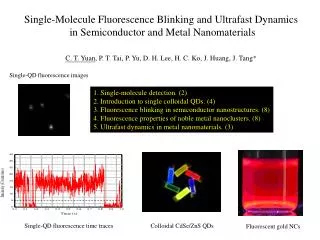
1 / 36
360 likes | 480 Vues
S ilicon D etectors in P article P hysics. (An introduction to semiconductor detectors). Paolo Lenisa Università di Ferrara and INFN - Italy. Tbilisi , July 11 th 2014. Particle detectors: history. The oldest particle detector …. High sensitivity to photons

E N D
Silicon Detectors in Particle Physics. (An introduction to semiconductor detectors). Paolo Lenisa Università di Ferrara and INFN - Italy Tbilisi, July 11th2014
Particle detectors: history The oldestparticle detector … • High sensitivity to photons • Good spatial resolution • Very large dynamic range (1:1014) + automatic threshold adaptation • Energy (wavelength) discrimination • Modest speed: Data taking rate ~ 10 Hz (incl. processing) retina
Particle detectors: history 1895 – Röntgen : Use of photographic paper as detector Photographic paper/film AgBr+ ‘energy’ metallic Ag (blackening) • Very good spatial resolution • Good dynamic range • No online recording • No time resolution 1909 - Geiger counter first electrical signal H. Geiger E. Rutherford 1912:- Wilson: Cloud chamber first tracking pulse • Water evaporates to the point of saturation • Lower the pressure • Super-saturated volume of air • Passage of charged particle condense tvapor • Droplets indicate particle track
Nowdays … LHC: 1 billion collisions/sec How do we see the collisions?
A look at the details… Example: measurement of B meson lifetime E.g. B J/Y Ks0 L Secondary vertex Primary vertex L = p/m c t • Look for B vertex and measure decay length – dist. between primary and secondary vert. • B mesons decay within 1-2 mm of interaction point (ct ~ 0.5 mm + relativistic time dilat.) • Need vertex detectors with excellent position resolution ~ 10 mm
How do we see the collisions?The Eyes of an Insect: 1 billion collisions/s 1,000 particles every 25 ns We need highly granular detectors that take pictures quickly, and manipulate the resulting data onboard and store it before shipping to a farm of computers
Silicon detectors The Eyes of a Piece of Silicon: The length of each side of the square is about the thickness of a piece of paper. Each eye is called a pixel
Silicon detectors Particle detection: requests • High-energyphysics detectors aimat: • Coverage of full solid angle • Measuremomentum and energy (p, E) • Identifyparticles (mass, charge) • Fast response • Particles are detected via theirinteraction with matter: • Chargedparticlesmainlyexcitation and ionization • Types of detectors: • Trackers (p) and vertex detectors • Thin (low-Z) material (gas, liquid or solid) • Calorimeter (E) • High-Z material (absorber)
Silicon detectors Principle of operation of a Silicon-eye: ionisation chamber • Particle deposits energy in detector medium positive and negative charge pairs (amount of charge can vary wildly from ~100 – 100 M e, typical is 24,000 e = 4 fC) • Charges move in electrical field electrical current in external circuit • Semiconductor detectors are solid-state ionization chambers
Silicon detectors Strips or Pixel - electrodes ~ 150V Principle of operation of a Silicon-detector: sequence • Chargedparticlecrossesdetector charged particle Positive voltage Ground +
Silicon detectors + + - - + - + + - + - + - ~ 150V Principle of operation of a Silicon-detector: sequence • Chargedparticlecrossesdetector • Createselectron hole pairs Strips or Pixel - electrodes
Silicon detectors + + - - + - + + - + - + - ~ 150V Principle of operation of a Silicon-detector: sequence • Chargedparticlecrossesdetector • Createselectron hole pairs • These drifttonearestelectrodes positiondetermination Strips or Pixel - electrodes
Solid state vs gas detectors • Ionization medium: gas, liquid or solid. • Gas: electron-ionpairs • Semiconductors: electron-holespairs • Solid State Detector: • ADVANTAGES • Energy for e-h pair < 1/10 gas ionization • Increasecharge good E resolution • Greater density • Reducedrange of secondary electron excellentspatialresoluton • To minimize multiple scattering short thickness • 300 mm 32000 e-ha pairsyealdsgood S/N DISADVANTAGES • Cost Area covered • Most cost in readout channels • Material budget Radiation length can be significant • Radiation damage Replace often or design very well
“Silicon-eyes” (detectors): many applications in digital Cameras to detect visible light insatellites to detect X-rays • synchrotrons: detection of X-ray and synchrotron radiation • nuclear physics measurement ofg-rays energy • heavy ion and particle physics: detection of charged particles • in medical imaging • in homeland security applications • What makes silicon detectors so popular and powerful?
Silicon detectors What’ssilicon?
Silicon detectors What’ssilicon? After Oxygen, Silicon is the 2nd most abundant element in Earth’s crust (>25% in mass) The crystalline structure is diamond cubic (FCC), with lattice spacing of 5.43 A Polysilicon consists of small Si crystals randomly oriented; in α-Si there is no long range order.
Silicon detectors Semiconductor basics: band structure • Isolated atoms brought together and form lattice wave functions overlap • Discrete atomic energy states shift and form energy bands • Properties of semiconductors depend on band gap
Silicon detectors Semiconductor basics: intrinsic charge carriers • Intrinsic semiconductors have no (few) impurities • At 0 K all electrons in valence band • no current flow if electric field applied • At room temperature, electrons excited to the conduction band • Important parameter of a detector : signal to noise ratio (SNR). • Twocontradictoryrequirements:! • Large signal low ionisation energy small band gap! • Low noise very few intrinsic charge carriers large band gap! • Optimal material: Eg≈ 6 eV. ! • Conduction band is almost empty at room temperature • Band gap small enough to create a large number of e-h+pairs. • Such a material exist, it is Diamond. too expensive for large detectors!.
Example: Estimate of SNR in an intrinsic Si-detector E.g. calculation for silicon:Mean ionization energy I0 = 3.62 eVmean energy loss per flight path: dE/dx = 3.87 MeV/cmintrinsic charge carrier density at T = 300 K ni = 1.45 · 1010 cm-3Assuming a detector with a thickness of d = 300 μm and an area of A = 1 cm2 • Intrinsic charge carrier at 300 K: Signal of a mip in such a detector: Number of thermal created e+ h- pairs four orders of magnitude higher than signal! How to detect a drop of water in the ocean ? Remove the charge carrier Depletion zone in reverse biased p-n junctions (DIODE)!
What are Si-diodes made of? • Silicon (group 4). • Each atom shares 4 valence electrons with its four neighbors. • The valence band has 8 electrons.• • At T=0K all electrons are in VB and CB is empty • As T increases some electrons jump the gap from VB to CB. n -Typematerial • In an n-type semiconductor, e- carriers obtained by adding an atom with 5 valence electrons: (As, Sb, P) • Electrons are the majority carriers • Donorsintroduce energy levels 0.01 eV below the CB • ⇒ Fermi Level moves close to CB. • In a p-type semiconductor, holes carriers are obtained by adding impurities of acceptor ions (B) • Holes are the majority carriers. • Acceptorsintroduce energy levels close to VB that ‘absorb’ electrons from VB, creating holes • => Fermi Level moves close to VB. p -Typematerial
p-n junction • p-n junction • Difference in the Fermi levels cause diffusion of excessive carries to the other material until thermal equilibrium is reached. • At this point the Fermi level is equal. The remaining ions create a space charge region and an electric field stopping further diffusion. • The stable space charge region is free of charge carries and is called the depletion region. Forward biasing. Applying an external voltage V with the anode to p and the cathode to n, e- and h+are refilled to the depletion zone. The depletion zone becomes narrower. Consequences: • The potential barrier becomes smaller by eV • Diffusion across the junction becomes easier • The current across the junction increases significantly. Reverse biasing. Applying an external voltage V with the cathode to p and the anode to n, e- and h+are pulled out of the depletion zone. The depletion zone becomes larger. Consequences: • The potential barrier becomes higher by eV • Diffusion across the junction is suppressed. • The current across the junction is very small (“leakage current”) (This is how we operate a semiconductor detector.)
How to detect a drop of water in the ocean ? remove ocean by blocking the DC current • Diodes reversely biased: very small leakage current flow
Leakage current • Detector operated with reverse bias, • Saturation current leakage current • Drift of the e- and h+ to the electrodes • Dominated by thermally generated e-h+pairs. • Due to the applied electric field they cannot recombine and are separated. Detector characteristics • Depletion voltage • Minimum voltage at which the bulk of the sensor is fully depleted. • Operating voltage is usually chosen to be slightly higher (overdepletion). • High resistivity material (i.e. low doping) requires low depletion voltage • Capacitance • Capacitancesimilarto parallel-platecapacitor • Fully depleted detector capacitance defined by geometric capacitance:
Operation: radiation damage Particles (radiation) interact with: a) electrons used for particle detection (temporarily effects only) b) atoms ofthe detector permanent changes (defects) in the detector bulk. A displaced silicon atom produces an empty space in the lattice (Vacancy, V) and in another place an atom in an inter lattice space (Interstitial, I). • Radiation induced leakage current • independent of impurities; every 7C • of temperature reduction halves current • cool sensors to -25C • type inversion” from n to p-bulk • increased depletion voltage • oxygenated silicon helps (for protons); • n+-in-n-bulk or n+-in-p-bulk helps • Charge trapping • the most dangerous effect at high fluences • collect electrons rather than holes • reduce drift distances
Example: strip detector Silicon detectors 768 Strip Sensors 80μm P++ N+ (high res) 300μm E Wires RO electronic Power supply Vbias~10’sV • Charged particles create e-h+ pairs in the depletion zone ( 30.000 pairs in 300 mm). • Charges drift to the electrodes. • Drift (current) creates signal amplified by an amplifier connected to each strip. • From the signals on the individual strips the position of particle is deduced. 22
Example: strip detector Silicon detectors • High events rate require fast signal collection: • Drift velocity of e- and h+ • For a detector thickness of 300 mm and over-depleted Vb= 50 V and 10 kW resistivity: • tcoll(e-)≈ 12ns • tcoll(h+) ≈ 35ns • Fast collection time helps radiation hardness: • Radiation damage to the Si bulk increases recombination rate. • Signal has to be collected quickly, before recombination. 24
Silicon detectors An application: Beam Polarization Measurement at PAX • Measurement of asymmetry in pd-elastic scattering • 2 Silicon Tracking Telescopes left and right of the COSY beam • Deuterium Cluster Target (dt=1014 atoms/cm2)
Silicon detectors An application: Beam Polarization Measurement at PAX • Measurement of asymmetry in pd-elastic scattering • 2 Silicon Tracking Telescopes left and right of the COSY beam • Deuterium Cluster Target (dt=1014 atoms/cm2) Top view Detectorsmeasure E, Θ, φ • Particleidentification • Selectionofelasticscattering • events cluster target
Silicon detectors An application: Beam Polarization Measurement at PAX Energyloss in 2. vs 3. layer Energyloss in 1. vs 2. layer dE (STT1_2) vs dE (STT1_3) dE (STT1_1) [MeV] dE (STT1_2) [MeV] deuterons deuterons protons protons dE (STT1_2) [MeV] dE (STT1_3) [MeV] Deuteron momentum vs. scattering angle Proton momentum vs. scattering angle P [GeV/c] P [GeV/c] Θ [deg] Θ [deg]
Silicon detectors An application: Beam Polarization Measurement at PAX • Events in left L↑↓andright R↑↓detector: t = 0s t = 12000s
Silicon detectors Results. Aimoftheexperiment. polarizationof a stored p-beam byinteractionwith a polarized H target (PAX session – Thu. 10.07) P measuredafter 0 s, 1.2x10⁴ s and1.6x104 s: Polarizationbuildwithtime: dP/dt=(4.8±0.8)×10-7 s
The future PAX silicon-eye Silicon detectors
The future PAX silicon-eye: a quadrant Silicon detectors READ-OUT LAYER 1 DISTRIBUTOR BOARDS ? READ-OUT LAYER 3 SENSORS LAYER 3 : PAX READ-OUT LAYER 2 SENSORS LAYER 2 : PAX SENSORS LAYER 1 : HERMES
One of the largest eyes ever built: the ATLAS detector ATLAS SCT 4 barrel layers, 2 x 9 forward disks 4088 double sided modules Total Silicon surface 61.1m² Total 6.3 M channels Power consumption ~ 50kW module
ATLAS detector: a sample picture Silicon detectors