Download

1 / 17
240 likes | 677 Vues
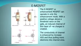
MOSFET. As switches. Regions of Operation. In analogue electronics, the MOSFETs are designed to operation in the pinch-off or saturation region. They are found in high speed and/or high power amplifiers, oscillators, current sources, etc .

E N D
MOSFET As switches
Regions of Operation • In analogue electronics, the MOSFETs are designed to operation in the pinch-off or saturation region. • They are found in high speed and/or high power amplifiers, oscillators, current sources, etc. • In digital electronics as well as power electronics, the primary use of a MOSFET are as a switch that connect and disconnect the circuitry at the drain of the MOSFET with the circuitry at the source. The modes of operation are the cut-off and triode/saturation regions. • However, the MOSFET has to move through the pinch-off/saturation region to get between these two regions of operation.
Operation of a Switch Typically, switches are used to connect and disconnect parts of one circuit with other parts of a circuit. Here is a schematic for a circuit where the switch is used to connect a light bulb to the dc power supply. The switch used in this case is a single pole, single throw (SPST). Questions: What is the power dissipated by the Light? Why would putting the switch between the Light and ground be dangerous when changing the light bulb?
Types of Switches • Two common ways to connect or disconnect one part of a circuit with another: • Mechanical – physical movement is require to make or break the connection. • Debounce circuits may be needed if the switch makes intermittent contact as its position is changed. • Electrical – the conductivity of a component is changed from insulating to conducting and back again (visa versa). • Useful when switching is done remotely. • They are required in hazardous locations where sparks can ignite fires. • The lifetime and reliability of an electrical switch is typically better than a mechanical switch. • Usually their size is smaller than mechanical switch to allow the same amount of current to flow through the switch.
NMOS Inverter One way to analyse the operation of an NMOS inverter is to consider the MOSFET to be a switch. Assume that Vin is either 0V or 5V.
Cut-off Region When Vin = 0V, which is equal to VGS and is less than VT, the MOSFET acts like an open circuit. No current flows through RD. The output voltage Vo =VDD.
Triode Transition When Vin = 5V, which is equal to VGS and is much greater than VT, the MOSFET acts like a very small resistor is connected between its source and drain. This resistor is known as RDSon. Current will flow through RD. The output voltage Vo =VDD– RDSonID~ VDD.
Important Input Voltages • NMOS • Vin = VGS • Transition between cut-off and pinch-off regions • VGS = VTN • Last input voltage that results in Vo = 5V • Transition between pinch-off and triode regions • VDS = VGS – VTN • PMOS • VGS = Vin – VDD • Transition between cut-off and pinch-off regions • VGS = - VTP • Last input voltage that results in Vo = 0V • Transition between pinch-off and triode regions • VDS = VGS – VTP
Enhancement Mode PMOS Switch Does the switch allow current to flow when VDD is 0V or 5V?
NMOS Depletion Mode Enhancement Mode and Depletion Mode Switches NMOS Enhancement Mode Normally OFF You have to apply a voltage to make VGS more positive than the threshold voltage for an NMOSFET to turn it on. • Normally ON • You have to apply a voltage to make VGSmore negative than the threshold voltage for an NMOSFET to turn it off.
NMOS Logic Determine the truth table for this circuit.
Power Losses • In a MOSFET switch, there are two ways in which power is dissipated: • Conductive loss • Switching loss
Conductive Loss • When the switch is on and drain current flows, there is power dissipated in RDSon. • We assume that no power is dissipated when the switch is off because no current flows (ideally). • We assume that the MOSFET is on half of the time. • We assume that the time that it takes to switch between on and off is very short compared to the length of time that the MOSFET is either on or off.
Switching Loss • The assumption is that the current and voltage in a MOSFET do not change instantly, no matter how fast you switch Vin between 0V and 5V. • We can also model this as the charging or discharging of the MOS capacitor. fswis the frequency that the MOSFET is switching from off to on and back again, tswonand tswoff are the length of time it takes to switch the MOSFET on and off, respectively, and COSS is one measurement of the parasitic capacitance of MOSFET. The values for tswon , tswoff, and COSSare found in the datasheet for the MOSFET that you use as a switch.
mbed • When you assign a value to a pin on the mbed, it causes a voltage to be applied to the MOSFET switch. VDD Vi R This is a MOSFET switch.