Download
1 / 29
290 likes | 371 Vues
Guided transmission of highly charged ions through capillaries in a polymer. R. Hellhammer, J. Bundesmann, D. Fink, V. Hoffmann, A. Petrov, Z. D. Pešić, V.A.Skuratov * ,B. Sulik + and N. Stolterfoht Hahn-Meitner-Institut Berlin, Germany

E N D
Guided transmission of highly charged ions through capillaries in a polymer R. Hellhammer, J. Bundesmann, D. Fink, V. Hoffmann, A. Petrov, Z. D. Pešić, V.A.Skuratov* ,B. Sulik+ and N. Stolterfoht Hahn-Meitner-Institut Berlin, Germany + Institute of Nuclear Research (ATOMKI), Debrecen, Hungary *Joint Institute for Nuclear Research, Dubna, Russia
Basics of the Capillaries The Low-Energy Ion Facility at the Ionenstrahllabor ( HMI ) Surprising results and the model for guiding High-Energy limit Summary and outlook Overview
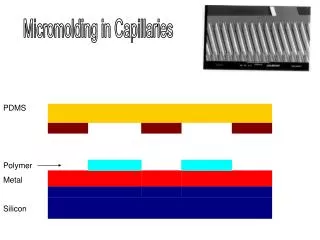
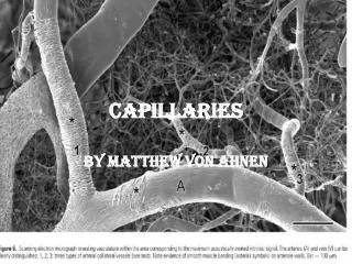
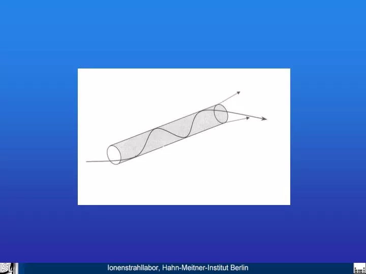
Basics of the capillaries AFM-Picture of the etched PET-Foils with uncovered surface PET: Polyethylen terephtalate
Basics of the capillaries AFM-Picture of the etched PET-Foils with uncovered surface SEM-Picture of covered PET surface with nanocapillaries PET: Polyethylen terephtalate
The Low-Energy Ion Facility at the Ionenstrahllabor ( HMI ) potential of ECR source : 0 to +17 kV 4 target places on GND-potential potential of beamline: 0 to -17 kV Beam production and beam transport
The Low-Energy Ion Facility at the Ionenstrahllabor ( HMI ) potential of ECR source : 0 to +17 kV 4 target places on GND-potential potential of beamline: 0 to -17 kV Beam production and beam transport Layout of the target chamber
Charge state distribution of ions transmitted through PET-Capillaries
Charge state distribution of ions transmitted through PET-Capillaries
Evidence for Capillary Guiding Angular distribution of Ne7+-Ions after passage through metallic capillaries at tilt angle of 0°
Evidence for Capillary Guiding Angular distribution of Ne7+-Ions after passage through metallic capillaries at tilt angle of 0° and 5°
Evidence for Capillary Guiding Angular distribution of Ne7+-Ions after passage through PET capillaries at tilt angle of 0° Angular distribution of Ne7+-Ions after passage through metallic capillaries at tilt angles of 0° and 5°
Evidence for Capillary Guiding Angular distribution of Ne7+-Ions after passage through PET capillaries at tilt angles of 0° and 5° Angular distribution of Ne7+-Ions after passage through metallic capillaries at tilt angles of 0° and 5°
Diameter dependencies Difference in angular distribution for different diameters
The model for Capillary Guiding Linear model : Propagation: Jp=Q(t)/tp Discharging: Jd=Q(t)/td
Time dependence of charging and discharging in PET-Capillaries Charging parameters: I=1nA ==10° Cap=100 nm c= 2.5 min 10 40
Time dependence of charging and discharging in PET-Capillaries Charging : I=1nA ==10° Cap=100 nm c= 2.5 min Discharging: d= 40 min 10 40
High-Energy-limit Energy dependence for 5° tilt angle
High-Energy-limit Energy dependence for 5° tilt angle
High-Energy-limit Energy dependence for 5° tilt angle
High-Energy-limit Energy dependence for 5° tilt angle
Outlook • Macroscopic Focusing : • Irradiate a foil bended over a • cylinder or a sphere Macroscopic Focusing The idea to use a capillary foil as a focusing element
Outlook • Macroscopic Focusing : • Irradiate a foil bended over a • cylinder or a sphere • the smoothed foil will give the • focus Macroscopic Focusing The idea to use a capillary foil as a focusing element
Outlook • Macroscopic Focusing : • Irradiate a foil bended over a • cylinder or a sphere • the smoothed foil will give the • focus • Mesoscopic Focusing : • Irradiate a flat foil • Press the irradiated and etched • foil on a matrix with mesoscopic • spheres or cylinders and stabilize • this geometry Macroscopic Focusing Mesoscopic Focusing The idea to use a capillary foil as a focusing element
Outlook Macroscopic Focusing Mesoscopic Focusing The technicalrealization for macroscopic focusing The idea to use a capillary foil as a focusing element