Download
1 / 93
980 likes | 1.16k Vues
Chapter 10 Error Detection and Correction. By Prof. Ashutosh S. Werulkar , Department of Electronics and Telecommunication Engg. St. Vincent Pallotti College of Engg. and Technology, Gavsi Manapur, Vardha Road, Nagpur 0712-2701934(R) 9970621934(M) Email: ashutoshwerulkar@yahoo.com/gmail.com.

E N D
Chapter 10 Error Detection and Correction ByProf. Ashutosh S. Werulkar, Department of Electronics and Telecommunication Engg.St. Vincent Pallotti College of Engg. and Technology, Gavsi Manapur, Vardha Road, Nagpur0712-2701934(R)9970621934(M)Email: ashutoshwerulkar@yahoo.com/gmail.com
Note Data can be corrupted during transmission. Some applications require that errors be detected and corrected.
10-1 INTRODUCTION Let us first discuss some issues related, directly or indirectly, to error detection and correction. Topics discussed in this section: Types of ErrorsRedundancyDetection Versus CorrectionForward Error Correction Versus RetransmissionCoding Modular Arithmetic
Note In a single-bit error, only 1 bit in the data unit has changed.
Note A burst error means that 2 or more bits in the data unit have changed.
Note To detect or correct errors, we need to send extra (redundant) bits with data.
Note In this book, we concentrate on block codes; we leave convolution codes to advanced texts.
Note In modulo-N arithmetic, we use only the integers in the range 0 to N −1, inclusive.
10-2 BLOCK CODING In block coding, we divide our message into blocks, each of k bits, called datawords. We add r redundant bits to each block to make the length n = k + r. The resulting n-bit blocks are called codewords. Topics discussed in this section: Error DetectionError CorrectionHamming Distance Minimum Hamming Distance
Example 10.1 The 4B/5B block coding discussed in Chapter 4 is a good example of this type of coding. In this coding scheme, k = 4 and n = 5. As we saw, we have 2k = 16 datawords and 2n = 32 codewords. We saw that 16 out of 32 codewords are used for message transfer and the rest are either used for other purposes or unused.
Example 10.2 Let us assume that k = 2 and n = 3. Table 10.1 shows the list of datawords and codewords. Later, we will see how to derive a codeword from a dataword. Assume the sender encodes the dataword 01 as 011 and sends it to the receiver. Consider the following cases: 1. The receiver receives 011. It is a valid codeword. The receiver extracts the dataword 01 from it.
Example 10.2 (continued) 2. The codeword is corrupted during transmission, and 111 is received. This is not a valid codeword and is discarded. 3. The codeword is corrupted during transmission, and 000 is received. This is a valid codeword. The receiver incorrectly extracts the dataword 00. Two corrupted bits have made the error undetectable.
Note An error-detecting code can detect only the types of errors for which it is designed; other types of errors may remain undetected.
Figure 10.7 Structure of encoder and decoder in error correction
Example 10.3 Let us add more redundant bits to Example 10.2 to see if the receiver can correct an error without knowing what was actually sent. We add 3 redundant bits to the 2-bit dataword to make 5-bit codewords. Table 10.2 shows the datawords and codewords. Assume the dataword is 01. The sender creates the codeword 01011. The codeword is corrupted during transmission, and 01001 is received. First, the receiver finds that the received codeword is not in the table. This means an error has occurred. The receiver, assuming that there is only 1 bit corrupted, uses the following strategy to guess the correct dataword.
Example 10.3 (continued) • 1. Comparing the received codeword with the first codeword in the table (01001 versus 00000), the receiver decides that the first codeword is not the one that was sent because there are two different bits. • 2. By the same reasoning, the original codeword cannot be the third or fourth one in the table. • 3. The original codeword must be the second one in the table because this is the only one that differs from the received codeword by 1 bit. The receiver replaces 01001 with 01011 and consults the table to find the dataword 01.
Note The Hamming distance between two words is the number of differences between corresponding bits.
Example 10.4 Let us find the Hamming distance between two pairs of words. 1. The Hamming distance d(000, 011) is 2 because 2. The Hamming distance d(10101, 11110) is 3 because
Note The minimum Hamming distance is the smallest Hamming distance between all possible pairs in a set of words.
Example 10.5 Find the minimum Hamming distance of the coding scheme in Table 10.1. Solution We first find all Hamming distances. The dmin in this case is 2.
Example 10.6 Find the minimum Hamming distance of the coding scheme in Table 10.2. Solution We first find all the Hamming distances. The dmin in this case is 3.
Note To guarantee the detection of up to s errors in all cases, the minimum Hamming distance in a block code must be dmin = s + 1.
Example 10.7 The minimum Hamming distance for our first code scheme (Table 10.1) is 2. This code guarantees detection of only a single error. For example, if the third codeword (101) is sent and one error occurs, the received codeword does not match any valid codeword. If two errors occur, however, the received codeword may match a valid codeword and the errors are not detected.
Example 10.8 Our second block code scheme (Table 10.2) has dmin = 3. This code can detect up to two errors. Again, we see that when any of the valid codewords is sent, two errors create a codeword which is not in the table of valid codewords. The receiver cannot be fooled. However, some combinations of three errors change a valid codeword to another valid codeword. The receiver accepts the received codeword and the errors are undetected.
Figure 10.8 Geometric concept for finding dmin in error detection
Figure 10.9 Geometric concept for finding dmin in error correction
Note To guarantee correction of up to t errors in all cases, the minimum Hamming distance in a block code must be dmin = 2t + 1.
Example 10.9 A code scheme has a Hamming distance dmin = 4. What is the error detection and correction capability of this scheme? Solution This code guarantees the detection of up to three errors(s = 3), but it can correct up to one error. In other words, if this code is used for error correction, part of its capability is wasted. Error correction codes need to have an odd minimum distance (3, 5, 7, . . . ).
10-3 LINEAR BLOCK CODES Almost all block codes used today belong to a subset called linear block codes. A linear block code is a code in which the exclusive OR (addition modulo-2) of two valid codewords creates another valid codeword. Topics discussed in this section: Minimum Distance for Linear Block CodesSome Linear Block Codes
Note In a linear block code, the exclusive OR (XOR) of any two valid codewords creates another valid codeword.
Example 10.10 Let us see if the two codes we defined in Table 10.1 and Table 10.2 belong to the class of linear block codes. 1. The scheme in Table 10.1 is a linear block code because the result of XORing any codeword with any other codeword is a valid codeword. For example, the XORing of the second and third codewords creates the fourth one. 2. The scheme in Table 10.2 is also a linear block code. We can create all four codewords by XORing two other codewords.
Example 10.11 In our first code (Table 10.1), the numbers of 1s in the nonzero codewords are 2, 2, and 2. So the minimum Hamming distance is dmin = 2. In our second code (Table 10.2), the numbers of 1s in the nonzero codewords are 3, 3, and 4. So in this code we have dmin = 3.
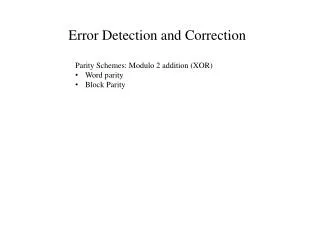
Note A simple parity-check code is a single-bit error-detecting code in which n = k + 1 with dmin = 2.
Figure 10.10 Encoder and decoder for simple parity-check code
Example 10.12 Let us look at some transmission scenarios. Assume the sender sends the dataword 1011. The codeword created from this dataword is 10111, which is sent to the receiver. We examine five cases: 1. No error occurs; the received codeword is 10111. The syndrome is 0. The dataword 1011 is created. 2. One single-bit error changes a1 . The received codeword is 10011. The syndrome is 1. No dataword is created. 3. One single-bit error changes r0 . The received codeword is 10110. The syndrome is 1. No dataword is created.
Example 10.12 (continued) 4. An error changes r0 and a second error changes a3 . The received codeword is 00110. The syndrome is 0. The dataword 0011 is created at the receiver. Note that here the dataword is wrongly created due to the syndrome value. 5. Three bits—a3, a2, and a1—are changed by errors. The received codeword is 01011. The syndrome is 1. The dataword is not created. This shows that the simple parity check, guaranteed to detect one single error, can also find any odd number of errors.
Note A simple parity-check code can detect an odd number of errors.
Note All Hamming codes discussed in this book have dmin = 3. The relationship between m and n in these codes is n = 2m − 1.