Download
1 / 29
300 likes | 320 Vues
DATABASE MANAGEMENT SYSTEM. Basic Definitions. Database: A logical coherent collection of data representing the mini-world such that change in the mini-world brings about change in database collected for a particular purpose and for a group of intended users. Data:

E N D
Basic Definitions • Database: • A logical coherent collection of data representing the mini-world such that change in the mini-world brings about change in database collected for a particular purpose and for a group of intended users. • Data: • Meaningful facts, text, graphics, images, sound, video segments that can be recorded and have an implicit meaning. • Metadata: • Data that describes data • File Processing System • A collection of application programs that perform services for the end-users such as production of reports • Each program defines and manages its own data • Database Management System (DBMS): • A software package/ system to facilitate the creation and maintenance of a computerized database. • Database System: • The DBMS software together with the data itself. Sometimes, the applications are also included. Database + DBMS
Evolution of DB Systems • Flat files - 1960s - 1980s • Hierarchical – 1970s - 1990s • Network – 1970s - 1990s • Relational – 1980s - present • Object-oriented – 1990s - present • Object-relational – 1990s - present • Data warehousing – 1980s - present • Web-enabled – 1990s - present
Purpose of Database Systems Database management systems were developed to handle the difficulties of typical file-processing systems supported by conventional operating systems
Disadvantages of File Processing • Program-Data Dependence • File structure is defined in the program code. • All programs maintain metadata for each file they use • Duplication of Data (Data Redundancy) • Different systems/programs have separate copies of the same data • Same data is held by different programs. • Wasted space and potentially different values and/or different formats for the same item. • Limited Data Sharing • No centralized control of data • Programs are written in different languages, and so cannot easily access each other’s files. • Lengthy Development Times • Programmers must design their own file formats • Excessive Program Maintenance • 80% of of information systems budget • Vulnerable to Inconsistency • Change in one table need changes in corresponding tables as well otherwise data will be inconsistent
Advantages of Database Approach • Data independence and efficient access. • Data integrity and security. • Uniform data administration. • Concurrent access, recovery from crashes. • Replication control • Reduced application development time. • Improved Data Sharing • Different users get different views of the data • Enforcement of Standards • All data access is done in the same way • Improved Data Quality • Constraints, data validation rules • Better Data Accessibility/ Responsiveness • Use of standard data query language (SQL) • Security, Backup/Recovery, Concurrency • Disaster recovery is easier
Costs and Risks of the Database Approach • Up-front costs: • Installation Management Cost and Complexity • Conversion Costs • Ongoing Costs • Requires New, Specialized Personnel • Need for Explicit Backup and Recovery • Organizational Conflict • Old habits die hard
Database Applications • Database Applications: • Banking: all transactions • Airlines: reservations, schedules • Universities: registration, grades • Sales: customers, products, purchases • Manufacturing: production, inventory, orders, supply chain • Human resources: employee records, salaries, tax deductions • Databases touch all aspects of our lives
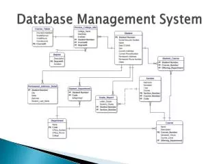
Levels of Abstraction View 1 View 2 View 3 • Many views, single conceptual (logical) schemaand physical schema. • Views describe how users see the data. • Conceptual schema defines logical structure • Physical schema describes the files and indexes used. Conceptual Schema Physical Schema • Schemas are defined using DDL; data is modified/queried using DML.
Example: University Database • Conceptual schema: • Students(sid: string, name: string, login: string, age: integer, gpa:real) • Courses(cid: string, cname:string, credits:integer) • Enrolled(sid:string, cid:string, grade:string) • Physical schema: • Relations stored as unordered files. • Index on first column of Students. • External Schema (View): • Course_info(cid:string, enrollment:integer)
Instances and Schemas • Similar to types and variables in programming languages • Schema – the logical structure of the database (e.g., set of customers and accounts and the relationship between them) • Instance – the actual content of the database at a particular point in time
Data Independence • Ability to modify a schema definition in one level without affecting a schema definition in the other levels. • The interfaces between the various levels and components should be well defined so that changes in some parts do not seriously influence others. • Two levels of data independence • Physical data independence:- Protection from changes in logical structure of data. • Logical data independence:-Protection from changes in physical structure of data.
Instances and Schemas • Similar to types and variables in programming languages • Schema – the logical structure of the database • e.g., the database consists of information about a set of customers and accounts and the relationship between them) • Analogous to type information of a variable in a program • Physical schema: database design at the physical level • Logical schema: database design at the logical level • Instance – the actual content of the database at a particular point in time • Analogous to the value of a variable • Physical Data Independence – the ability to modify the physical schema without changing the logical schema • Applications depend on the logical schema • In general, the interfaces between the various levels and components should be well defined so that changes in some parts do not seriously influence others.
Database Languages Data Definition Language (DDL) • Specification notation for defining the database schema • DDL compiler generates a set of tables stored in a data dictionary • Data dictionary contains metadata (data about data) • Data storage and definition language – special type of DDL in which the storage structure and access methods used by the database system are specified Data Manipulation Language(DML) • Language for accessing and manipulating the data organized by the appropriate data model • Two classes of languages • Procedural – user specifies what data is required and how to get those data • Nonprocedural – user specifies what data is required without specifying how to get those data
Database Users • Users are differentiated by the way they expect to interact with the system • Application programmers – interact with system through DML calls • Sophisticated users – form requests in a database query language • Specialized users – write specialized database applications that do not fit into the traditional data processing framework • Naïve users – invoke one of the permanent application programs that have been written previously • E.g. people accessing database over the web, bank tellers, clerical staff
Database Administrator • Coordinates all the activities of the database system; the database administrator has a good understanding of the enterprise’s information resources and needs. • Database administrator's duties include: • Schema definition • Storage structure and access method definition • Schema and physical organization modification • Granting user authority to access the database • Specifying integrity constraints • Acting as liaison with users • Monitoring performance and responding to changes in requirements
Data Models • A collection of tools for describing: • Data • Data relationships • Data semantics • Data constraints • Object-based logical models • Entity-relationship model • Object-oriented model • Semantic model • Functional model • Record-based logical models • Relational model (e.g., SQL/DS, DB2) • Network model • Hierarchical model (e.g., IMS)
Entity-Relationship Model • The basics of Entity-Relationship modelling • Entities (objects) • E.g. customers, accounts, bank branch • Attributes • Relationships between entities • E.g. Account A-101 is held by customer Johnson • Relationship set depositor associates customers with accounts • Widely used for database design • Database design in E-R model usually converted to design in the relational model which is used for storage and processing
name ssn lot Employees ER Model Basics • Entity: Real-world object distinguishable from other objects. An entity is described using a set of attributes. Each attribute has a domain. • Entity Set: A collection of similar entities. E.g., all employees. • All entities in an entity set have the same set of attributes. (Until we consider ISA hierarchies, anyway!) • Each entity set has a key. Weak Entities: A weak entity can be identified uniquely only by considering the primary key of another (owner) entity.
name ER Model Basics ssn lot Employees since name dname • Relationship: Association among two or more entities. E.g., Attishoo works in Pharmacy department. • Relationship Set: Collection of similar relationships. • An n-ary relationship set R relates n entity sets E1 ... En; each relationship in R involves entities e1 E1, ..., en En • Same entity set could participate in different relationship sets, or in different “roles” in same set. super-visor subor-dinate ssn budget lot did Reports_To Works_In Employees Departments
E-R Diagrams • Rectangles represent entity sets. • Diamonds represent relationship sets. • Lines link attributes to entity sets and entity sets to relationship sets. • Ellipses represent attributes • Double ellipses represent multivalued attributes. • Dashed ellipses denote derived attributes. • Underline indicates primary key attributes (will study later)
Mapping Cardinality Constraints • Express the number of entities to which another entity can be associated via a relationship set. • Most useful in describing binary relationship sets. • For a binary relationship set the mapping cardinality must be one of the following types: • One to one • One to many • Many to one • Many to many
Mapping Cardinalities One to one One to many Many to one Many to many
Participation Constraints • Does every department have a manager? • If so, this is a participation constraint: the participation of Departments in Manages is said to be total (vs. partial). • Every Department entity must appear in an instance of the relationship Works_In (have an employee) and every Employee must be in a Department • Both Employees and Departments participate totally in Works_In name name dname dname since ssn did did budget budget lot Departments Employees Manages Works_In since
Keys • A super key of an entity set is a set of one or more attributes whose values uniquely determine each entity. • A candidate key of an entity set is a minimal super key • Customer_id is candidate key of customer • account_number is candidate key of account • Although several candidate keys may exist, one of the candidate keys is selected to be the primary key. • Alternate keyis the candidate key which are not selected as primary key. • Foreign keyare the attributes of an entity that points to the primary key of another entity.They act as a cross-reference between entities. • Composite Key consists of two or more attributes that uniquely identify an entity. Non-key attributes are the attributes or fields of a table, other than candidate key attributes/fields in a table. • Non-prime Attributes are attributes other than Primary Key attribute(s)..
Relational Model Example of tabular data in the relational model:
Relational Model (Basic) Therelational modelused the basicconceptof a relation or table. Tuple:- A tuple is a row in a table. Attribute:-An attribute is the named column of a relation. Domain:- A domain is the set of allowable values for one or more attributes. Degree:- The number of columns in a table is called the degree of relation. Cardinality:- The number of rows in a relation,is called the cardinality of the relation.
Integrity Constraints Integrity constraints guard against accidental damage to the database, by ensuring that authorized changes to the database do not result in a loss of data consistency. • Domain Constraints:- It specifies that the value of each attribute x must be an atomic value from the domain of x. • Key Constraints:- Primary Key must have unique value in the relational table. • Referential Integrity:-It states that if a foreign key in table A refers to the primary key of table B then, every value of the foreign key in table A must be null or be available in table B. • Entity Integrity:- It states that no attribute of a primary key can have a null value.