Download
1 / 9
90 likes | 237 Vues
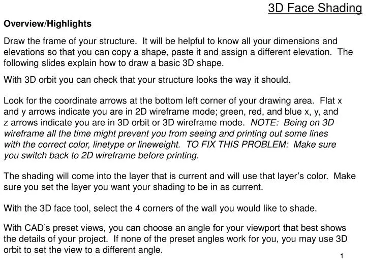
3D Face Shading. Overview/Highlights. Draw the frame of your structure. It will be helpful to know all your dimensions and elevations so that you can copy a shape, paste it and assign a different elevation. The following slides explain how to draw a basic 3D shape.

E N D
3D Face Shading Overview/Highlights Draw the frame of your structure. It will be helpful to know all your dimensions and elevations so that you can copy a shape, paste it and assign a different elevation. The following slides explain how to draw a basic 3D shape. With 3D orbit you can check that your structure looks the way it should. Look for the coordinate arrows at the bottom left corner of your drawing area. Flat x and y arrows indicate you are in 2D wireframe mode; green, red, and blue x, y, and z arrows indicate you are in 3D orbit or 3D wireframe mode. NOTE: Being on 3D wireframe all the time might prevent you from seeing and printing out some lines with the correct color, linetype or lineweight. TO FIX THIS PROBLEM: Make sure you switch back to 2D wireframe before printing. The shading will come into the layer that is current and will use that layer’s color. Make sure you set the layer you want your shading to be in as current. With the 3D face tool, select the 4 corners of the wall you would like to shade. With CAD’s preset views, you can choose an angle for your viewport that best shows the details of your project. If none of the preset angles work for you, you may use 3D orbit to set the view to a different angle.
BASICS ON CREATING A 3D SHAPE This is an overview on creating a 3D shape using a very basic figure: a cube. For more complex figures, apply the same concepts, but you should know the layout of each component and its elevations. Start out with the footprint, or a bottom layer, of your drawing, then copy it and change the elevation. Objective: draw a 10’x10’x10’ cube. Use the polygon icon to draw a 10’x10’ square. Click the Properties icon (or go to Modify menu – Properties) to easily manipulate elevations.
Click on your figure, right click, then select copy with base point. Select a point in your drawing to use as a base point (OSNAP is helpful in this case), then paste the figure using the same point as the insertion point. Although you will only see one figure, the copied figure will be over the original figure. You will notice if you drag the top one. You now have one square on top of the other, both with the same elevation. Click on the top square to change its elevation (dashed lines indicate that it is selected). Overwrite the elevation in the properties box to what you need it to be. In this case, we will add 10’ to the base elevation to complete our 10’x10’x10’ cube.
Using 3D Orbit (View menu, go to 3D Orbit – Free Orbit) or a view angle (through View – 3D Views or the View toolbar or the drop-down window in the 3D Navigation toolbar), you will see your figure shaping up. Keep your view at an angle where you can see all 4 corners of a face of your cube that you will shade. IMPORTANT: Set to current the layer where you want your shading to be. Your shading will acquire the color of the layer it belongs to.
In the Draw menu, go to Modeling – Meshes – 3D face Alternatively, you can use the 3D face icon if you have it in one of your toolbars. Make sure you hit Enter when finished (pressing Esc will discard your outline). Begin drawing your cube’s face by selecting all 4 corners of a face.
In the View menu, go to Visual Styles – Conceptual There is also a Visual Styles toolbar you could use. You will see the first face of your cube!
You may need to rotate the drawing to a different angle in order to see the next four corners of the face you are going to shade. If you remain in Conceptual visual style, you will see the shading as you assign it. Complete the process as described on slide 5. To exit isometric view mode, switch to 2D wireframe view style , and select the Top preset view.
In this example, we will draw a concrete slab surrounded by 2 ft walls, and a ramp. We want to show the contractor the extents of the wall footings, which are 6” thick, and where it’s only 5” thick for just the slab. We also want to illustrate the 6” of subgrade material.
After drawing the frame of the structure, 3D shading was assigned to the walls, the footing, the concrete slab, and the subgrade layer. Each component was assigned a different layer, thus the different colors.