Download
1 / 30
300 likes | 481 Vues
Rapid Prototyping of Photonic Crystal based THz Components towards Integrated THz Micro-System Ziran Wu Department of Physics Department of Electrical and Computer Engineering wzr@email.arizona.edu. Outline. 1. Background / Motivations Photonic Crystal based Components

E N D
Rapid Prototyping of Photonic Crystal based THz Components towards Integrated THz Micro-System Ziran Wu Department ofPhysics Department of Electrical and Computer Engineering wzr@email.arizona.edu
Outline 1 • Background / Motivations • Photonic Crystal based Components • Polymer-Jetting Rapid Prototyping • Realizations of Various THz Components • Components Systematic Integration • Conclusions
THz Background 2 • Coverage in IR and optical blind conditions • Concealed object screening • Unallocated communication region • Gigabit data capacity • High bandwidth • Scattering loss < optical regime • THz bio-medical image: Identify tissue, tumor, DNA, etc. • THz chemical signatures: Explosives * B. Ferguson, XC. Zhang, Nature Mater., 1, 26 (2002)* Peter H. Siegel, IEEE Trans. Microwave Theory Tech., 50, 910 (2002) * D. Arnone et. al., Physics World, 0953-8585, April 2000* Optics.org, analysis article, Oct. 28, 2002
Motivations 3 We need THz componentsSource, detector, filter, waveguides, antenna, quasi-optics, materials… We need integration of componentsPre-alignments, packaging, systematic fabrication… We need universality and customizabilityPlug-and-play, easy customization… We need THz rapid prototyping Results THz Micro-system Source Detector DUI
Photonic Crystal based Components 3 3 - - D Photonic Crystal D Photonic Crystal Radiation Core Radiation Core Normal Planck Normal Planck spectrum from spectrum from Intensity Intensity amorphous object amorphous object IR IR l l PBG structure optimized PBG structure optimized PBG structure optimized Enhanced THz Enhanced THz emission emission to generate strong to generate strong to generate strong Intensity Intensity emission peak in the THz emission peak in the THz emission peak in the THz band. band. band. l l 4 • Photonic Crystal (PhC) • Periodic arrangement of dielectric/ metallic structures • Bragg Diffraction among lattices • Forbidden wave propagation in certain frequency band • Scalable dimensions with frequency Band Gap THz thermal radiation source PBG fiber electron accelerator * H. Xin et al, IEEE Trans. Antennas Propag., 56, 2970 (2008) * C. Sears et al, Proceedings PAC07, THPMS052, Albuquerque, NW, 2007
PBG Components Continued 5 Sub-wavelength effective-medium lens Antenna with PhC substrate * K. F. Brakora et. al., IEEE. Trans. Antenn. Propag.,55, 790 (2007) * Peter de Maagt, et. al., IEEE Trans. Antennas Propag., 51, 2667 (2003) Line-defect waveguide and bend Woodpile defect horn antenna * K. Busch, Phys. Report444, 101 (2007) * Nielsen et.al.,OTST-2009, MB5, March 2009 * A. Weily et. al., IEEE Trans. Antenn. Propag.87, 151114 (2005)
THz 3-D Rapid Prototyping 6 • Objet (TM) polymer jetting prototyping • Layer-by-layer printing of structures • Printing resolution 42um (x) by 42um (y) by 16um (z) • UV curable model material Support material removable by water flushing (Matt mode) • Non-support-material printing available (Glossy mode) • Possibility of mixing various printing materials to achieve arbitrary spatial material properties • Rapid prototyping of arbitrary shapes • Alignment and assembly not necessary • Mass production achievable with very low cost
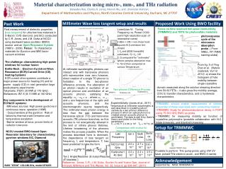
Build Materials Characterization 7 THz Time Domain Spectrometer Dispersion Compensation Ultra-fastLaser Control Unit THz Transmitter THz Detector Collimating Optics • Photoconductive antennas as transmitter/receiver • Ultra-fast gating enables time-domain measurement • Covering 50GHz to 1.2THz with 10GHz resolution • Transmission / Reflection setup available * Ziran Wu, J. App. Phys., 50, 094324 (2008)
Build Materials THz Properties 8 Vero Family • Multiple-reflection excluded by using thick slabs • Comparable EM properties in one family of polymers • Large enough refractive index contrast to open PBG • Acceptable material loss
Filter: Woodpile Structure 9 Printed woodpile prototype * S.Y. Lin et.al,, Nature 394, 251 (1998) • Dielectric / metallic rods with woodpile stacking formations • Square rod width w= 352um and periodicity d= 1292um • Printing took about 30 minutes; Consumable cost of approximately $10 • Excellent agreements with simulations on both gap positions and depths
Filter: Johnson Structure 10 Printed Johnson Structure prototype * S. G. Johnson and J. D. Joannopoulos, Appl. Phys. Lett.77, pp. 3490-3492, 2000 • Hole layer – air holes in dielectric Rod layer – dielectric rods in air Triangle lattice formation in each layer • Practically difficult to fabricate • Triangular lattice constant x= 1346um Air hole radius r= 500um Air hole height h= 1713um Rod / hole layer height t= 1071um • Fabrication well verified by characterization * Ziran Wu, Opt. Express, 21, 16442-16451 (2008)
Waveguide: Hollow-core PCF Design 11 Band Gap 1 Band Gap 2 Frequency fa/c0 Only modes above the light line can propagate Wave vector kza/2Pi Cross-Section View Energy Distribution • Triangular-lattice array of air cylinders in a dielectric background • Center core defect to form the wave tunnel • Defect modes within the band gap of the complete PhC* • 90% energy concentration in the core low radiation and material losses HE11 mode * MIT Ab-Initio MPB package
Waveguide: Wave-port Simulation 12 Band Gap 1 Band Gap 2 Power Loss Factor • PEC circular waveguide, TE11 mode feeds • 84mm long polymer PBG waveguide • Lattice pitch 3mm, air hole radius 1.3mm, center core radius 4.2mm • Transmission loss as low as 0.04 dB/mm in 1st pass-band; Low return loss
Waveguide: Gaussian Beam Excitation 13 Transmitted PowerEvaluation Plane Gaussian Beam Incidence Beam waist 3mm ( 90% coupling to HE11 mode) 112GHz • Identical coupling to free space at input and output interfaces • Transmitted power exponentially decays as waveguide length increases (Neglect multiple-reflections) • Calculated loss matches well with wave-port simulation Semi-log plot Slope = Power Loss Factor * GEMS conformal FDTD package
Waveguide: Modal Simulation / Coupling 14 Mode simulation based on effective index method Modal E-field Profile 74% power coupled to HE11 modewith a beam waist of 4.2mm • Modal field overlapping with Gaussian beam get coupling efficiency • Optimum beam waist ~ 2.7mm, over 90% coupling to HE11 mode • Plano-convex lens fabricated by rapid prototyping to reach optimal beam size * Lumerical MODE Solution
Waveguide: Fabrication and Bench Setup 15 • Fabricated THz waveguide samples (Glossy modes) • Quasi-optics to focus the beam waist to 2.7mm
Waveguide: Characterization Results 16 • Waveguides of 50, 75, 100, 125, and 150 mm long characterized • Time-gating ensures no multiple reflection in the calculation • Guided mode resonance seen in all waveforms • Four pass bands clearly show up around 105, 123, 153, and 174 GHz
Waveguide: Power Loss Factor 17 Linear fitting at 107GHz • Linear fitting of power (dB) vs. waveguide length to get loss factor • Extracted loss agrees pretty well with the beam incidence simulation • Downshift of about 7 GHz probably due to fabrication error (need support material)
Antenna: Photonic Crystal Horn 18 Circular waveguide TE11 feedingPolymer loss: constant conductivity 0.23 Not bad considering 1.5dB material loss 4.2mm flared to 8mm aperture radii (12.4 degree)35mm optimized horn length along axis
Antenna: Radiation Patterns 19 Far-Field Radiation Pattern of Phi= 0º Cut (x-z plane) 114GHz 164GHz • Directional beam obtained at two working frequencies • Comparable main beam angle with copper horn; Side-lobe level not as low • Works much better than copper horn (over-moded) at high frequency
Transition: Waveguide-to-Planar Circuit 20 • Tapered wedge transit to microstrip substrate • PEC flares on top and bottom shrink the field spread • Mstrip single-mode operation up to 120GHz (400um trace width 127um substrate thick) • Tapered cone helps impedance matching • Power directed into the dielectric rod waveguide (TIR guiding) • Circular-to-square cross section transition • Smooth surface generated by HFSS
Transition: Waveguide-to-Planar Circuit 21 • -6.75dB insertion loss best at 108GHz; low return loss • Excluding 2.1dB waveguide loss 2.3dB loss at each transition section • About 4dB more loss if polymer material loss included
Sub-wavelength Effective Medium 22 * K. F. Brakora et. al., IEEE. Trans. Antenn. Propag.,55, 790 (2007) Capacitive Estimation of the Permittivity Tensor Effective medium with artificially designed anisotropy
Source: Photonic Cavity Array 23 500um • Array of cubes with ~ 200um sides • Printed by polymer-jetting and metalized via sputtering • Electroplating or electro-less deposition for 3-D metallization • Complete band gaps between THz resonance frequencies • Strong and sharp thermal emission at THz
Source: PBG e-Accelerator at THz? 24 Very cheap prototyping Arbitrary fiber / coupler design Need a THz power source to drive it * R. England et al., Bob Siemann Symposium and ICFA Workshop, July 8th, 2009
Integrated THz Micro-System 25 Waveguide Antenna Filter Source Metamaterial Transition to planar-circuits THz ChipTHz Sample THz Micro-System
Conclusions 26 • THz rapid prototyping technique demonstrated • THz filter, waveguide, and antenna fabricated by prototyping • Characterizations of these components show good agreements with the designs • Prototype-able transition-to-planar circuit, effective medium, and source proposed and under study • Systematic integration of the aforementioned building blocks leads to THz micro-system
Acknowledgement Graduate Student Ian Zimmerman 1 For metal sputtering on cavity array Wei Ren Ng 2 For sample fabrication and post-process Faculty Prof. Hao Xin 1 Prof. Richard Ziolkowski 3 Prof. Michael Gehm 2 For help on both EM modeling and sample fabrications 1 Millimeter Wave Circuits and Antennas Lab 2 Non-Traditional Sensors Lab 3 Computational Electromagnetics Lab
Other PhD Work • Thermal radiation from THz photonic crystals • THz characterization of carbon nanotube ensemble and on-substrate thin films • De-metallization of single-walled carbon nanotube thin film with microwave irradiation • Frequency-tunable THz photonic crystals using liquid crystal • “Lab-on-chip” transmission-line characterization circuits