Download
1 / 40
400 likes | 483 Vues
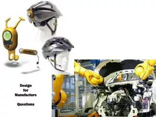
The IMPACT Center Addressing Challenges for Future IC Design and Manufacture. Kameshwar Poolla Electrical Engineering & Computer Sciences February 12, 2009 poolla@berkeley.edu 510.520.1150. TexPoint fonts used in EMF. Read the TexPoint manual before you delete this box.: A A A A A.

E N D
The IMPACT CenterAddressing Challenges for Future IC Design and Manufacture Kameshwar Poolla Electrical Engineering & Computer Sciences February 12, 2009 poolla@berkeley.edu 510.520.1150 TexPoint fonts used in EMF. Read the TexPoint manual before you delete this box.: AAAAA
Outline • The Landscape What is happening today & what we imagine will happen tomorrow • The IMPACT Center Who we are & what we do • A Tasting Five Research Projects • A Success Story Equipment Control for optimized across wafer CD uniformity • Opportunity Beckons Clip calculus as a new paradigm
The Evolving Landscape • New Technologies Multiple patterning, Immersion, metal gates … • New Materials Zr-doped TaOx, MoN, WN … • Design/Manufacturing Interface breakdown Need data driven models of manufacturing for design Need design aware manufacturing practice • More fabless companies Need to deal with foundries, manage information Model of manufacturing becomes even more important • Complexity is the new bottleneck
The Target – 22 nm and beyond • Expected technologies • Quadrupole/Quasar illumination • Immersion Litho • Double patterning • Non-planar devices • Exotic gate materials • New transistor designs • Tools that will be necessary • Distributed Computation: parallel or cellular processors • Data mining, Machine Learning, fast parameter extraction • Modeling expertise to capture effects at various space and time scales • Process expertise to drive modeling effort • Design expertise to impact electrically relevant performance
The Fantasy … Metal interconnect Tungsten plugs Poly Si gates Di-electric (insulator) not shown Si bulk
Three Challenges • You don’t always get what you want • Interactions and The Radius of Influence • The Computation Bottleneck
You don’t always get what you want • Manufacturing realities cannot be modeled by simple rules • Partial solution – better predictive “models” of the manufacturing process, hierarchical abstractions • Models must be simple enough to run very, very fast • Link Manufacturing model upstream to EDA tools • Static timing, RC extraction, power/noise/area optimization
The Radius of Influence 90 nm 32 nm OPC/RET changes at center of red zone affects AD patterns across red area
The Radius of Influence • OPC/RET will get even more computationally expensive • Design rules will become extremely complex • Interactions across features • Interactions between layers • Interactions among processes • Partial solution – Filter through design & process • Concentrate on design-critical hotspots • Concentrate on process sensitive hotspots • Automated hot-spot detection and repair • Mask fragmentation for multiple patterning/exposure
The Computation Bottleneck • Design cycle iterations are expensive • Process models must be run very fast • Design rules are now 2000+ pages! • Partial solution – stress scalability and computation in all aspects of our research
Our Response – the IMPACT Project • IMPACT http://impact.berkeley.edu/ Integrated Modeling Process And Computation for Technology • Long term, pre-competitive, interdisciplinary research • Supported by 21 leading Companies and State of California • 17 Faculty + 23 Grad Students + 5 Post-docs + 3 Undergrads • 9M$ budget • Major Equipment Donations • Centura 200 epitaxial tool from Applied Materials • EM Suite Simulation Package from Panoramic Technologies • Wafer/Mask processing credits: Spansion, SVTC, Dupont, Photronics
The Faculty Team Alon, Elad EECS UCB Integrated System Design, Mixed-signal ICs Chang, Jane ChE UCLA Plasma mechanisms, feature modeling Cheung, Nathan EECS UCB Plasma modeling, diagnostics, surface intenractions Dornfeld, David ME UCB CMP modeling, mechanics aspects Doyle, Fiona MatSci UCB CMP modeling, chemistry effects Komvopoulos, K. ME UCB Surface Polishing, Nanomechanics Graves, David ChE UCB Plasma modeling, diagnostics, surface interactions Gupta, Puneet EE UCLA DfM, Optimization, Variability Analysis Haller, Eugene MatSci UCB Dopant and Self-Diffusion in Si and SiGe Alloys Hu, Chenming EECS UCB Device Modeling, Variability Analysis Kahng, Andrew EECS UCSD DFY, DFM, algorithms King, Tsu-Jae EECS UCB Novel Electron Devices Lieberman, Michael EECS UCB RF sources and E&M plasma modeling Neureuther, Andrew EECS UCB Litho, Pattern Transfer, Modeling/Simulation Poolla, Kameshwar ME/EE UCB DFM, Modeling, Computation, Control, Metrology Spanos, Costas EECS UCB IC Process Metrology, Diagnosis and Control Talbot, Jan CE UCSD Chemical-Mechanical Planarization
Lithography Andy Neureuther Novel Technologies Tsu-Jae King-Liu Design-Manufacturing Interface Puneet Gupta Etch Jane Chang CMP Dave Dornfeld Our Research Five Inter-connected Research Themes:
Litho: Through-Focus fast-CAD Pattern matching 2D Lateral Weight DRC Att-mask 90o edge effects Standard Cell Interactions Lateral Influence Functions Compact model though focus
DMI: Non-Rectangular Gate Modeling Four components Poly gate imperfections: well-studied (SPIE’05) Active rounding: (ASPDAC’08) Line-end shortening: (DAC’07) Line-end tapering: (PMJ’08) Key elements Equivalent length/width models Separate modeling for Ion and Ioff Use Models Design power/performance analyses Interactions with design rules and OPC Shaping transistor channels for better devices Case Study: DFF
RF Z ESC 10 mTorr 80 mTorr 500 mTorr Energy (eV) Energy (eV) Energy (eV) 100 nm 100 nm 100 nm Plasma: Surface, Feature, Reactor Scale Models Particle-in-cell, Monte Carlo collision Molecular dynamics simulations and expts Monte Carlo feature scale model coupling with reactor model Energy and angle of all species Fundamental surface reactions Origin of surface evolution Resist etched by 150 eV Ar+; VUV; at 100C Ion and hot electron density ~ 1000 nm Neutral energy distributions 2 nm hole in Si etched with 200 eV CF2+ Couple models at various scales to understand plasma-surface interaction and predict profile evolution
Comprehensive CMP Modeling Integrated chemo-mechanical modeling of material removal Data structure for capturing multiscale behavior: tree based multi-resolution meshes Pattern Evolution Model for HDPCVD STI Chip Layout Evolution Pattern density
Transistor Design for Reduced Variability Very steep retrograde doping is needed to reducesVT due to RDF Engineer the channel material (Si1-xGex) to control dopant diffusion. Evolve the planar MOSFET into a tri-gate structure Improve channel gate control, improve robustness to process-induced variations, improve transistor performance Lg Planar MOSFET: GATE DRAIN GATE-SIDEWALL SPACER Simulated I-V Curves: atomistic doping (100 cases) vs. continuum doping (nominal case) SOURCE ISOLATION OXIDE Lg Tri-Gate MOSFET: GATE DRAIN GATE-SIDEWALL SPACER Gate electrode covers 3 sides of the channel SOURCE ISOLATION OXIDE
A Success Story – CD Control • Critical Dimension (CD) • Width of printed lines • Varies across wafer, and wafer-to-wafer • greatly influenced by post-exposure bake and etch • CD variability is the performance metric for pattern transfer • Want: to reduce CD variability • How? Making each process step spatially uniform is not possible • Our approach: Control manipulate PEB temperature spatially to compensate for downstream systematic across-wafer CD variation due to etch
Temperature sensors • Unprecedented Spatial and temporal resolution • Used to model PEB plates and effect of temp on CD • Models are used for Control
The Value of Control • Post-Exposure-bake • Key process step • Directly impacts critical dimension uniformity • Control spatial temperature of bake plate • Yesterday ± 0.3 °C Today ± 0.15 °C • Result:1 nm reduction in CD spread • Benefit: mid-sized fab in 1st year of product lifecycle ~$3/die * 200 die/wafer * 20,000 wafer/mon * 12 mon/yr = 144 M$ per year !!
CD Uniformity Control Before After 2.3 nm 1.0 nm
Opportunity Beckons – Clip Calculus • Basic Assertion: Working with clips is more efficient and natural than distances/rules • Potential opportunities for clip calculus • Faster printability analysis • Inverse Litho • Clips • Could be non-rectangular • Standard cells, macros, etc … • Core “Central” part of a clip • Context “Outer” part of a clip • Library Collection of clips • Core & Context depend on target application • Ex: DRC, OPC, Printability analysis • The problem: algorithms to efficiently deal with clips clip • OPC re-use • Faster DRC mask context core
DRC Clean core Context Ex: DRC • Current Practice • DRC brick is 2,000 pages and exploding • Conventional rule-based DRC at 22nm will be unmanageable • Alternatives:Work with clips not distances • Leverage the speed of pattern match • Produce library of good, bad, or graded patterns • Use library to detect and correct new design layouts • Open problems • Clip-based DRC, Hybrid Rule-Clip DRC, • Redundancy removal in rules, Correction! • Core and Context • Core is the region that is DRC clean given the fixed Context • Context may not be DRC clean as that depends on Context(Context) • Use Case • Library of known DRC clean (in core) clips • In a mask M, use PatternMatch against library L • Can eliminate the core of every matched clip • Will have to do DRC on remaining areas
Clip Metrics • What is a good metric on the space of clips? • Difficult problem • Must also extend to Alternating PSM, Attenuating PSM • Metric must also be computable in the language of rectangles • Standard pixel based metrics fail: Treats each pixel independently Does not respect proximity • When are two clips similar? If the images in Silicon of the core of both clips are similar • Suggests that we need application dependent weightings • Exposure & Dose sensitivity analysis will have different weights
Some Computational Problems Mask M, clip c, library , N = number of clips • ExactMatch: Find all instances of c in M • RoughMatch: Find all sub-patterns p in M with • VolFind: Find Area(core union) • WhereNext: Find largest rectangle not covered by clips • ExactTile: Tile M with core of clips drawn from library i.e. choose tiling to maximize Area(core union) For 3 & 4 we have N log(N) algorithms with N log(N) pre-processing time • Many other very interesting problems • Net-list covering by clips • Dynamic programming for inverse lithography • These are all problems in CS, with a twist • Must compute based on rectangles, respect hierarchy • Must work on huge problems
In Summary… • The IC revolution will continue • The method of designing ICs will have to change • Design and Manufacturing Interaction is much more complex • Challenges include • Design & Process Complexity • Modeling & Computation • IMPACT will play a key role • Technological value to our sponsors • Real educational experience for our students • Multi-disciplinary cutting edge research opportunities for our faculty http://impact.berkeley.edu/ Feedback: poolla@berkeley.edu
Some computational problems … • There are other very interesting problems • Net-list covering by clips • Library generation • Dynamic programming for inverse lithography • These are all problems in CS, with a twist • Must compute based on rectangles • Must respect hierarchy • Must work on huge problems • Clip-based paradigms have good potential • OPC re-use • Faster DRC, RC extraction, printability analysis • Faster hot-spot detection and repair • Fast mask fragmentation for multiple-patterning • Many challenging problems • Metrics • Use cases • Fast Algorithms
Plasma: Research Integration n + + Ion Angular and Energy Distribution (Particle in Cell modeling: M. Lieberman) Species Distribution (Reactor-Scale Modeling: (D. Graves and J. Chang) n + n + n Photoresist Reaction Mechanism (Beam Experiments: D. Graves) Profile Evolution (Feature Scale Modeling: J. Chang) LER issue for 193nm PR 193nm PR 248nm PR X. Hua, et. al, J. vac. Sci. Technol. B 24, 1850 (2006) • Define testbeds for research integration (LER, Gate Stack Etch, PVD ….. etc.)
Litho: Electrical Test Patterns & Circuits Multi-Student Test Masks Collaborative Platform for DfM Novel Leakage Testing Screening for Focus Sensitive Candidates Focus Test Patterns On-Line Database Sim/Exp
Segmented Bulk MOSFET for Reduced Variability Multi-gate structures provide for improved control of short- and narrow-channel effects, and reduce STI-induced stress effects Steep retrograde channel doping reducesVT variation due to SDF Segmented bulk MOSFET combines these features to reduce variability in performance, while retaining compatibility with strained-Si, high-k/metal gate & active body biasing technologies 100 atomistic simulations LG = 20nm EOT = 0.9nm VDS = 1V Planar Bulk MOSFET Segmented Bulk MOSFET σVT = 27.1 mV σVT = 10.1 mV DRAIN CURRENT [A/20nm] DRAIN CURRENT [μA/20nm] DRAIN CURRENT [A/ 20nm] DRAIN CURRENT [μA/20nm] 30 30 20 20 • Continuum doping ID-VG • Continuum doping ID-VG 10 10