Download
1 / 24
240 likes | 617 Vues
From H8 Test-beam to Muon System Commissioning. 1 st North American ATLAS Physics Workshop Tucson, AZ - December 20-21, 2004 Claudio Ferretti – University of Michigan. Outline. Aim: this is a ‘physics workshop‘, so focus on detector calibration and validation

E N D
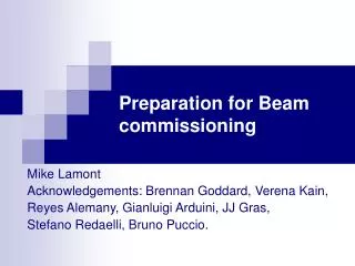
From H8 Test-beam to Muon System Commissioning 1st North American ATLAS Physics Workshop Tucson, AZ - December 20-21, 2004 Claudio Ferretti – University of Michigan
Outline Aim: this is a ‘physics workshop‘, so focus on detector calibration and validation • H8 setup description & objectives • US contributions to the H8 test beam • Review of a few test beam muon results (software/trigger in Moore/Amstrong’s talk) • Phase I chamber certification • Plans for calibration work in next phases Claudio Ferretti – University of Michigan
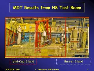
Whole H8 Test Beam Layout Claudio Ferretti – University of Michigan
H8 Muon Endcap Layout TGC EOS/L EMS/L Barrel chambers EIS/L Claudio Ferretti – University of Michigan
H8 setup in 2004 • 8 Barrel MDT (2 BIL, 2 BML, 2 BOL + 1 BIL + 1 BOS) Full FE electronics ( 1 MROD) and alignment system 1 BILon rotating support for r(t) relations 1 BOS MDT+RPC for combined test beam and noise test • 6 Barrel RPC (4 BML and 2 BOL) only ¼ of the 2 towers equipped with New PAD boards Total 2880 MDT channels with 8 CSM and 2 MROD • 6 Barrel MDT (2 EI, 2 EM and 2 EO) • Fully equipped with FE electronics 1 MROD • Full (almost “absolute-calibrated”) alignment system Total 1920 MDT channels with 6 CSM and 1 MROD • 3 TGC (2 doublets, 1 Triplet) + full on chamber electronics • CSC and MBPS magnet between EI and EM station Claudio Ferretti – University of Michigan
H8 Muon System Objectives • Full scale integration of the whole electronics chain (tube HH mezz CSM MROD ROS) • Readout of the sensors through ELMB/DCS • Validation of the whole alignment system • First staging of combined muon detectors (MDT, RPC, TGC, CSC) • Test of the muon triggers bunch ID efficiency and second coordinate • Integration of multiple detector readout into the Data stream. Claudio Ferretti – University of Michigan
US Contributions • ISR Early chambers setup + leak certification and dark current test (by UM) • Detector: 4 MDT (Boston and Seattle) + CSC from BNL • Electronics: CSMs, Motherboards, Mezzanine cards + support hardware from UM • Alignment system from Brandeis • Physicists and engineers • Software for operational & diagnostic analysis • Data analysis Claudio Ferretti – University of Michigan
Individual Contributions My deep apologies to every institution/single who worked hard and not mentioned here • UoM: Dan Levin, US H8 coordinator from 2002 • UoM: J. Chapman, J. Gregory, B. Ball, T. Dai: electronics (CSM-2, Motherboard, software, ...) • UoM: R. Avamidrou shifts and on site operations • Harvard: J. Oliver Mezzanine test setup station + software • Tufts: K. Sliwa, M. Wolfer, S.Tudorovova online logbook and data analysis • Seattle: J. Rothberg DB coordinator + CXDB work Claudio Ferretti – University of Michigan
A Few Trigger Results • Central Trigger Processor latency ~ 5 BC (target 4 BC) • Successful MuCTPI in 25 ns runs (Oct) • Fast (LVL2) LVL1 trigger with global pattern recognition and better Pt estimation (Look Up Table) within a Region of Interest. • TrigMoore (Event Filter) Based on Moore for seeded reconstruction from RoI of either LVL2 or LVL1 and precise Pt determination Claudio Ferretti – University of Michigan
H8 Analysis Tasks • Evaluation of tube-channel stability, functionality, efficiency, noise, mortality • Sagitta resolution • Alignment system tests: • Temperature induced chamber motions • Controlled translations and rotations • Absolute alignment • Combined detectors system • Test reconstruction software (Moore, Muonboy in Athena + Mutrak) Claudio Ferretti – University of Michigan
Chamber functionality 2003: • 35 dead tubes in 12 chambers • ~14 % of both hedgehog cards not working • Discovered problem with CSM “pair mode” • Many noisy tubes 2004: • 10 dead tubes (9 in barrel chambers) • Developed MECCA continuity test • CSM “edge mode” updated CSM & MROD • Evaluated common mode noise (G. Blanchot) • Replace mezzanine and threshold per ASD Claudio Ferretti – University of Michigan
Endcap Beam Profile • Hit distribution: hodoscope (~flat) 10x10 cm2 • No dead channels (holes) • A few noisy channels (only 1 large spike) (S.Todorova &Tufts) Claudio Ferretti – University of Michigan
L y TDC Spectrum & Wire sag t0 ± 80 ns/√#ev y= wire displacement (m) x= distance from center (m) L= tube length (m) ρ = wire density (g/cm3) R = wire radius (μm) T= wire tension (g) tmax ± 200 ns/√#ev Drift time Claudio Ferretti – University of Michigan
t0 Run Δt0 Run Drift Time & T0 stability Example EIL (Marcin Wolter) ML#1 ML#2 Channel # Mezzanine # 19 HODO runs; threshold - 40 mV Δt0 respect mezzanine average Claudio Ferretti – University of Michigan
Chamber efficiency Example for one EMS chamber Claudio Ferretti – University of Michigan
Alignment plots • - Very strong • T-dependence • -Sensors images • reproduce the • movement • 180 images • (83 KB/image) • per cycle (5’) • many GB/day DB saves only analysis result • (J. Rothberg) Optical sensor (BCAM) 1μm (Azimuthal EO) Temperature 5 days Claudio Ferretti – University of Michigan
2003 Sagitta Baseline Measurement After ~0.5 mrad rotation Aug 6-11: Controlled displacement + long term T distortions Reconstructed Sagitta Corrected Sagitta RESULT Alignment and muon tracks give the same relative sagitta variations in 10-20 μm (D. Levin) Resolution improved by 27 % points still referenced to July 19 ! Claudio Ferretti – University of Michigan
2004 Endcap Sagitta Results Track with nominal geometry sagitta follows T (~ alignment) ARAMyS: geometrical corrections: large chambers (ex.) 45 parameters - Temperature expansion:86 μm/ºC - Chamber translations and rotations - Deformations: torsion, cross plate sags and elongations (RO &HV) . . . All runs : 10x10 cm2, Hodoscope trigger, magnetic field (-600A) RMS=15 μm(14 μm @ small trigger acceptance)↔ ARAMyS correction ~ alignment (~10-20 μm) Sagitta ~ -157 μm close to absolute alignment precision 120-150 μm (D. Pomarède) RMS=15 μm S = -157 μm RMS=104 μm ΔS~400 μm S = -184 μm RMS=21 μm S = -159 μm RMS=14 μm Claudio Ferretti – University of Michigan
An example of indirect results Double peak Ramsauer dip in the cross section for E(e-) ~ 0.35-0.60 eV at E=1.6 KV/cm giving a longer mean free path. 2% water clear the second peak. Ar-CO2(93%-7%) H2O percentage 0.5, 1.0,1.52.0 Ar-CO2 (93-7%) 3 bar, 1 vol/day HV=3080V Nitrogen shifts the 2nd peak at higher fields smaller times. Ar(93%)-CO2(7%) N2 percentage 0.5, 1.0,1.5 2.0, 2.5, 3.0 Rachel Avramidou Using Garfield simulation Claudio Ferretti – University of Michigan
Wire sag correction Difference in Drift Times (ns) H8 BILR θ=40º 96 μm wire sag Double tail fit Δ(DT) = 199 μm T-max affected by wire sag>150 μm Wrong gas Ar-CO2 93-7 93.6-6.6 % (method in B184) (Ed Diehl, Dan Levin, Ashley Thrall) Wire Displacement (μm) Claudio Ferretti – University of Michigan
Endcap Phase I Certification H8 experience important in pre-commissioning: ex.grounding HV connector http://www.atlas.physics.lsa.umich.edu/docushare/dsweb/Get/Document-2295/ Endcap DB document • Mechanical drawings • DAQ/tests configuration • Data 20 DB tables • Web interface ~ 5,200 records/MDT 600K fields/MDT CERN DB Claudio Ferretti – University of Michigan
80 UM Endcap in Phase I ASD noise cut=35ns 30709 tubes + 11 dead (4 in B180 accident) Claudio Ferretti – University of Michigan
Next steps • Phase II (BW, SW, EIL4): DCS, B-sensor & Alignment connectivity/operability. • HV off Threshold/All test (mezz ID) • HV off Random trigger, @ -50mV, noise test • HV on Random trigger, @ -40mV, noise test DB • Measure relative t0 for each channel (Δt0~2 ns) • Burn-in: 2 weeks/sector (mortality of components, stability, DB baseline results, monitoring parameters) • Phase III: • Relative timing with TGC chamber • RT functions with and without B-field (single beams) • verify the RT function models. Needed detailed studies together with trigger system Claudio Ferretti – University of Michigan
Conclusions • Encouraging chamber validation results • Castor ~ 3 TB from ~ 6,500 runs: combined analysis still on (H8 workshop in February) • Successful test beam shows • Stable electronics with low noise • Consistent & stable tube parameters (t0,drift time) • Working “muon system” calibration • Large effort needed for data monitoring already at commissioning stage • A lot of work to (re-)organize run log-file and DB (Conditions DB, Phase 1-2-3, AMDB, …) Claudio Ferretti – University of Michigan