Download
1 / 29
300 likes | 786 Vues
Spectrum Microwave High Linearity Amplifiers . The Spectrum Family of Businesses. Microwave Components & Systems Business | SpectrumMicrowave.com Amplifiers, Mixers, Switches, Oscillators & Sources RF/Microwave Filters, Diplexers & Multiplexers, Integrated Multifunction Modules

E N D
The Spectrum Family of Businesses Microwave Components & Systems Business | SpectrumMicrowave.com • Amplifiers, Mixers, Switches, Oscillators & Sources • RF/Microwave Filters, Diplexers & Multiplexers, Integrated Multifunction Modules • Thin Film Substrates, Hybrid Assembly Services EMI Filter & Components Business | specemc.com • EMI Surge Suppression Components & Modules • Power Line Filters & Power Entry Modules • Interconnect Devices • Terminal Blocks & Passive Components Power Management Systems | specpower.com • Power Management & Distribution Systems • AC & DC Power Strips • Power Monitoring Equipment: Environmental, Electrical, Security, Mechanical Sensors & Controls Business | specsensors.com • Potentiometers, Temp Sensing Probes, Surge Current Limiters
30 Years of Design & Manufacturing Experience • Over 600 Microwave employees (75 Engineers) 1 | Columbia, MD Acquired July 2002 (FSY) 2 | Delmar, DE Acquired February 2004 (Salisbury Engineering) 3 | Palm Bay, FL Acquired October 2004 (Q-bit) 4 | Philadelphia, PA Acquired February 2005 (Amplifonix) 5 | State College, PA Acquired January 2007 (EMF Systems) 6 | Marlborough, MA Acquired September 2008 (Satcon-Film MicroElectronics) Acquired December 2009 (IDT-MicroNetworks) 7 | Auburn, NY Acquired December 2009 (IDT-Creative Electric) 8 | Nashua, NH Acquired June 2010 (Sage Labs) 7 8 6 5 4 1 2 3
Product Line Overview Hybrid Components, Mixers & Advanced Technologies • In-house thin & thick film capability - Complete testing & ESS capability • 30 year heritage design database - Rapid military to low cost conversion • Quick turn prototypes (2-4 days) - Modular assemblies Filter Components & Integrated Filter Assemblies • Complete filter solutions - 20 year heritage design database • In-house machining - Focused design centers for quick turn prototypes • Complete testing & ESS capability (2-4 weeks) Frequency Sources & Integrated Microwave Assemblies • 80% critical component content - 25 IMA engineers with 22 years average experience • In-house development of ATE
Component Overview Leading designer and manufacturer of RF components and integrated microwave assemblies (IMAs) • Products including: • Amplifiers (Low Phase Noise, LNAs, High Dynamic Range, Power) 1 MHz to 18 GHz • Mixers from DC to 26 GHz • Voltage Control Oscillators (VCOs) 25 MHz to 18 GHz • Dielectric Resonator Oscillators (DROs) 2 GHz to 20 GHz • RF & Microwave Filters • Switched Filter Banks, Integrated Products • Rotary Joints, Phase Shifters, Couplers • Markets served include: • Military Electronics, Avionics, Aerospace and Commercial
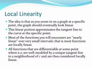
Engineering for Excellence • Using the expertise of our team of Microwave Amplifier Design Engineers, our focus is not only on meeting the customer’s requirement, but on exceeding their expectations. • Other companies talk about High Linearity …we let our designs speak for themselves. • For example…
Amplifier Designs • Our Push-Pull Design Techniques,coupled with transistors that havebeen selected for high linearitycharacteristics, enable SpectrumEngineers to achieve this incredibleperformance including IP2 valuesof +120 dBm.
Amplifier Designs In order to understand the benefit’s of Spectrum’s outstanding performance, a little background on the theory of linearity is in order. The second-order term can be expanded as: The same trigonometric identity can be used to expand the third-order terms yielding:
Amplifier Designs • All superheterodyne receivers utilize an intermediate frequency (IF) between the input of the antenna and the amplification stages. When a single tone is received it is processed so that the signal can be more easily demodulated. RF Input 800 MHz IF Output 100 MHz VCO 700 MHz
Amplifier Designs The theoretical third order intercept is determined when we input 2 signals into the input signal port of our receiver.
Amplifier Designs • These signals then pass thru a mixer which produces tones that are the differences or sums of those signals referred to as the IM (intermodulation) products. • Some of these tones are within the IF band which will pass right thru the IF amplifier (IFA) which follows this mixer.
Amplifier Designs • The IM products which play a pivotal role in the signal processing is the 2nd harmonic which is related to the 3rd order tones, which then leads us to the 3rd order intercept.
Amplifier Designs • Now, as signal strength is increased by 1 dB, the IM products also increase, but by 3 dB. • The third order intercept point is the output signal level (thru extrapolation) at which the 3rd order tones would achieve an equal amplitude level, as the desired input frequencies. 3rd Order Intercept Point Saturated Power Power Out Original Tone 3rd Order Power In
Amplifier Designs • If we reach this theoretical point, our mixer output signal becomes distorted. Thereby, any increase in input signal strength will not generate an increase in output signal strength. • This is a problem, because now, the frequency near the signal we want to detect has distorted the information on the carrier signal. This in turn causes interference susceptibility. 2nd Order Intercept Point 3rd Order Intercept Point Saturated Power Power Out Original Tone 3rd Order 2nd Order Power In
Amplifier Designs • This again goes back to the IM products which cause this distortion, and the noise that follows, and is not a result of the level of our signals. 3rd Order Intercept Point Saturated Power Power Out Original Tone 3rd Order Power In
Amplifier Designs • Once again, the third order intercept point is a calculation of the level of our signal vs. that of the unwanted IM products. Higher linearity offers less distortion. • The better the IP3, the more notable the receiver's ability to separate and discern several tones that are processed simultaneously inside our passband. 2nd Order Intercept Point 3rd Order Intercept Point Saturated Power Power Out Original Tone 3rd Order 2nd Order Power In
Amplifier Designs • The Third Order Intercept Point is determined by plotting input power vs. the output power. The 2 curves are then drawn, one for a nonlinear product and one for the linear amplified signal. 2nd Order Intercept Point 3rd Order Intercept Point Saturated Power Power Out Original Tone 3rd Order 2nd Order Power In
Amplifier Designs • Another way to look at it, the IP3 is a figure of merit that characterizes a receiver's tolerance to several signals that are present simultaneously inside the desired passband. • The IP3 is a power level, typically given in dBm, and it is closely related to the 1 dB compression point. Both IP3 and the 1 dB compression point are meaningful only when given in relation to the noise floor. 2nd Order Intercept Point 3rd Order Intercept Point Saturated Power Power Out Original Tone 3rd Order 2nd Order Power In
Amplifier Designs • The method to achieve a highly linear circuit is by means of a push-pull design. This is accomplished by splitting the signal through 2 identical amplifiers, then combining the signal at the output end.
Amplifier Designs • The center tapped transformer at the input end splits the signal evenly, thus the two amplifiers are driven 180 degrees out of phase. After combining the 2 signals at the output transformer, this equal phase shifting transformation creates a cancelling of the even order harmonics, thus generating a cleaner signal.
Amplifier Designs • …and Second Order Intercept values like this…
Amplifier Designs • …and consequently IP3 values like this.
+ 7 6 . 0 + 7 5 . 5 + 7 5 . 0 + 7 4 . 5 + 7 4 . 0 + 7 3 . 5 + 7 3 . 0 + 7 2 . 5 + 7 2 . 0 + 7 1 . 5 + 7 1 . 0 + 7 0 . 5 + 7 0 . 0 S t a r t 2 0 M H z S t o p 5 0 0 M H z Amplifier Designs For added savings, our LCA (Lower Cost Amplifier) designs are able to produce IP2 values as high as +75 dBm.
Amplifier Designs • The challenge comes in play when two neighboring signals say a few MHz apart are received. Separating the signals will be a difficult job for the receiver. The higher two neighboring signals will be. 0 F1 F2 -10 -20 -30 Spectrum Output (dBm) -40 -50 -60 -70 -80 0 50 100 150 200 250 300 350 400 450 500 Frequency (MHz)
Amplifier Designs • Normally, higher-order products (thirds & seconds) are not seen with the same signal strength as the fundamental frequency. These tones are then viewed and perceived as distortion. 0 F1 F2 -10 -20 -30 Spectrum Output (dBm) 2F1 2F2 -40 -50 -60 3F1 3F2 -70 -80 0 50 100 150 200 250 300 350 400 450 500 Frequency (MHz)
Amplifier Designs • Note that if f1 and f2 are tones which are very close to one another (those 2 neighboring tones that were very close to the fundamental frequency), the 2( f1 - f2) tones are still close to the fo. Third and even more difficult second order products are extremely difficult to remove through filtering. 0 F1 F2 -10 -20 -30 F1 + F2 Spectrum Output (dBm) F2 – F1 2F1 2F2 -40 -50 2F2 – F1 2F1 + F2 2F2 + F1 2F1 - F2 -60 3F1 3F2 -70 -80 0 50 100 150 200 250 300 350 400 450 500 Frequency (MHz)
Amplifier Designs • Spectrum Engineers have the experience and expertise to offer the highest performance, highest linearity amplifiers the industry has to offer. We can even customize our design to meet demanding requirements and non-standard package options. Spectrum Microwave the industry’s High Linearity Specialists.
Design & Development Process Simulation & Design 1 Logistics 2 6 Specification Development 3 Testing 5 4 Manufacturing Prototyping