Download
1 / 13
130 likes | 140 Vues
Experimental Study of Free GaInSn Jet in M-TOR. Xiaoyong Luo (UCLA) Presented at APEX Electronic Meeting February 5, 2002. OUTLINE. Introduction Experimental Facility Description of Test Article Magnetic Field of the Flux Concentrator Numerical Simulation Conclusions. Ga Inlet.

E N D
Experimental Study of Free GaInSn Jet in M-TOR Xiaoyong Luo (UCLA) Presented at APEX Electronic Meeting February 5, 2002
OUTLINE • Introduction • Experimental Facility • Description of Test Article • Magnetic Field of the Flux Concentrator • Numerical Simulation • Conclusions
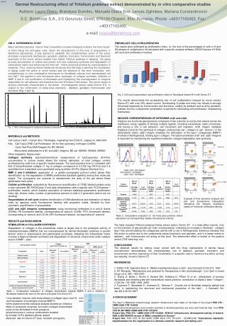
Ga Inlet Flow Meter Iron block Concentrator Circle disk Concentrator Supporter Ga Outlet Argon Gas Experimental Facility 1. Magnetic Torus Liquid Metal MHD flow test facility (MTOR) • 24 electromagnets arranged in a magnetic torus geometry, a 3400A/180V DC power supply, and a 16 liter actively pumped Ga-In-Sn flow loop • At a maximum current of 3400A, the field strength is about 0.6T at inboard 2. A Magnetic field concentrator is added into the facility (M-TOR) to increase the local field strength 3. Flow meter diagnostic
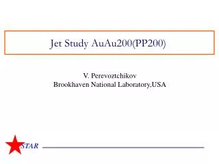
5mm Nozzle Transparent area Cone-shape Main Test Article Description 1. The test article is composed of 3 sections (1) A nozzle to provide a 5mm round jet (2)A transparent enclosure to prevent Ga oxidation (3)A cone-shape receiver to minimize splashing 2. Experiments have been conducted in two test articles configurations • a circular version • a rectangular version Unit: mm
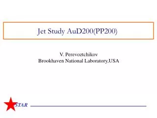
Iron Block Slots Flux Concentrator Assembly • The concentrator assembly includes a pair of large iron circle disks (not shown), which grasp the flux and redistribute it into a small iron block • The field strength depends on the distance between the pair Unit: mm
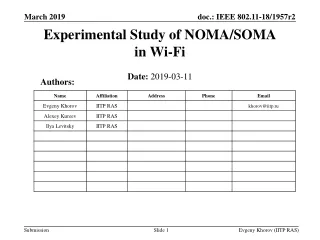
Maximum Point Maximum Gradient Magnetic Field Strength inside the Flux Concentrator • The magnetic field increases as the current passing through the coils increases • A Gauss meter is used to measure the field strength at 7 locations • The maximum magnetic field is ~ 1.1T • The maximum gradient of the magnetic field is ~ 10T/m Note:Distance means distance away from the edge of the concentrator
Video 1 for Round Test Article • Most of the view is blocked by the iron flux concentrator. Only flow outside the edge of the concentrator can be seen. • The Maximum Magnetic Field is ~ 1.1T( at the midplane of the concentrator) • A gradient exists between the inside and outside of the concentrator. A gradient of 33T/m is detected
Video 2 for Rectangular Test Article • The Maximum Magnetic Field at the midplane is ~ 0.9T at 2600A • The gradient is ~ 10T/m • Slots were cut in the iron concentrator along the gradient region to provide jet deflection measurements • The jet location is indicated by the bright spot (jet can not be seen)
Momentum Equation Maxwell’s Equations Ohm’s Law conservation law Poisson Equation Numerical Simulation • Governing Equations
Convergence critical Numerical Simulation • Numerical Methods Key Points: (1) An iterative computation to Ohm’s law was applied and a Poisson equation of the scalar potential was adopted in the numerical procedure. (2) Two-order central difference scheme was used (3) VOF method was used to track free surface
V=10m/s T=0.9T 5cm 10cm g T’=10 T/m Computational Results • Ga inlet velocity is10m/s • A constant magnetic field of 0.9T is assigned for the first 5cm, followed by a field gradient of 10T/m for the rest of 10cm • Computation domain is 15cm 2cm6cm ( about 70,000 meshes) 3-Dimensional VelocityProfile
t=0.025s t=0.015s t=0.02s t=0.01s X-direction Velocity Contours
Conclusions 1. Numerical simulation predicts a strong MHD effect. Jet deflects more than experimental observation. Near-term effort is to resolve this discrepancy. 2. Diagnostics for measuring jet deflection will be improved