Download
1 / 18
180 likes | 287 Vues
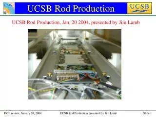
Rod Production. Rod Production, April 9 2004, presented by Jim Lamb (UCSB). Rod Production. Note: Rod component schedule covered in Regina’s talk. What is a rod?. Substructure for modular assembly of tracker barrel. 688 rods will be installed into a barrel much like the one in the picture.

E N D
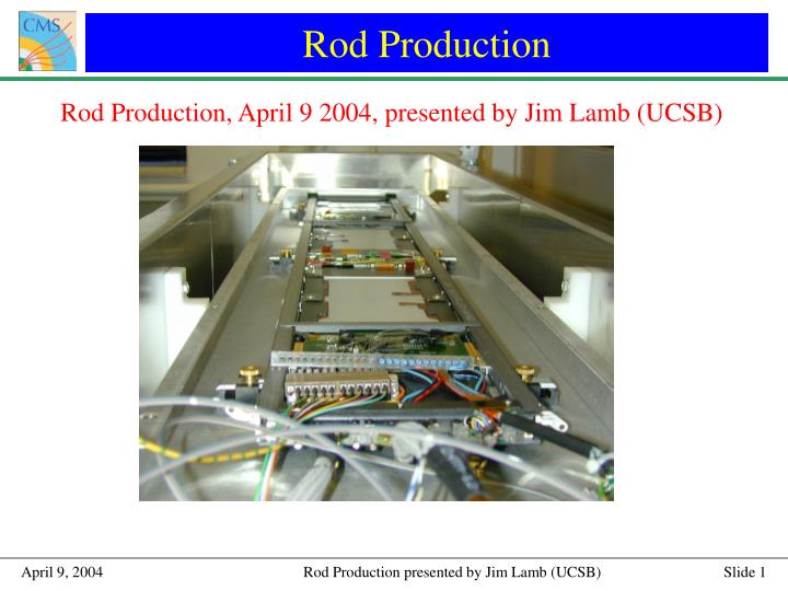
Rod Production Rod Production, April 9 2004, presented by Jim Lamb (UCSB)
Rod Production Note: Rod component schedule covered in Regina’s talk.
What is a rod? • Substructure for modular assembly of tracker barrel. • 688 rods will be installed into a barrel much like the one in the picture.
What is a rod? • Barrel is grouped into 96 control rings, each containing 5-10 rods. • Rods use token-ring protocol to communicate with data acquisition electronics. • Redundancy architecture allows control ring to operate even in case multiple non-consecutive failure.
Rod as it Arrives at US Sites • Major components are Command and Control Unit (CCU), and Analog Opto-hybrids (AOH). • CCU handles communication between rods, and between rod and readout electronics. • AOH converts module’s electrical output to optical signal. • Both of these components, as well as electrical connectivity of the whole, are tested at CERN prior to shipping. • Carbon-fiber frame produced in Helsinki, and assembly of CCU’s AOH’s and support electronics at CERN.
Rod Testing Flow Chart • Very conservative module installation (“assembly”) time estimate is 2 hours for single-sided rod, 3 hours for double-sided rod. The planned assembly of 2 rods/day won’t be stressful.
Rod Assembly • Module placed on bare rod using handling tools developed at UCSB (S. Kyre). • Handling tools developed here are used at CERN. • Six rods assembled at UCSB. One “dummy” rod assembled and disassembled multiple times at FNAL.
Rod Testing Flow Chart • Components most likely to fail are modules, optohybrids, and connectors. • Modules are built by us and are already extensively tested. • An apparatus to independently test optohybrids is on order, and we have spares on hand if needed. • We’re gaining experience in connector failure by the extensive handling of rods in the ramp-up phase.
Single Rod Test Stand • Used for functionality test after assembly. • Test box provides dry, dark, and electrical isolated environment • Also used for cold-test of individual rods (this test is not part of regular production). • Connects to rod burn-in chiller for cooling.
Single Rod Test Stand • Status: complete at UCSB, except that we are planning to purchase a second, smaller chiller so it can be run completely independently of burn-in chiller. • Nearing completion at FNAL.
Rod Testing Flow Chart • Rod burn-in very important. • Only cold-test of entire rod substructure. • First time every rod component is subjected to cold, long-term test. • See Paul Tipton’s talk.
US Multi-Rod LT Stands • Up to 8 rods run for 3 days of thermal cycling (room temp to –20C and back). (Burn-in hardware and interlock software developed and assembled by University of Rochester) • Rods controlled and read-out with software already written for module test. Adaptation of the software to this larger task is ongoing. • Data will be adapted so that initial module test (ARCS) criteria can be applied and module quality re-verified.
US Multi-Rod LT Stands • Status: UCSB stand is complete. FNAL burn-in box is complete, but lacks rod power supplies from CERN. Rod readout software not complete, but it is possible to run burn-in at reduced pace during ramp-up. • See Paul Tipton’s talk.
Rod Testing Results • Faults clearly seen. • Three rods have been read out so far. • For one rod (so far) we did a head-to-head comparison with ARCS readout. • More statistics needed in order to know how best to test rod. • Difference in noise height between two halves of module is due to uneven laser gain. This is one of the issues being resolved in readout software. ARCS Rod Readout
Status Summary • Single rod test stand fully equipped at UCSB. FNAL’s single rod test stand is currently being assembled. • Six complete rods assembled at UCSB, including one double-sided and one single-sided six-chip. • FNAL has experience assembling “dummy” rod. • Rod burn-in hardware complete at UCSB. Complete at FNAL except for rod power supplies. • Rod thermal-cycled to –20C.
Further Work • First FNAL assembly of production rods. Waiting on shipment of seven rods from CERN, expected in May. These rods should be final production rods. • Completion of rod readout software so that burn-in is as automated as possible. The lead developer set the target date for a beta version at May 1. I estimate two months of testing from there to smooth out all problems with the software. • Commissioning of burn-in stand with full capacity.
Further Work • Implementation of adapting ARCS testing criteria to long-term Rod testing data. • Some further work on the tooling to make module-to-rod connector connections. • The FNAL and UCSB engineers handling rod assembly will meet at UCSB for training.
Conclusion • We are capable of the planned production rate of two rods per day per site. • Planned burn-in capacity of 8 rods per 3-day thermal cycle has enough throughput. This capacity is achievable. • We expect to finish preparations this summer.