Download
1 / 9
90 likes | 254 Vues
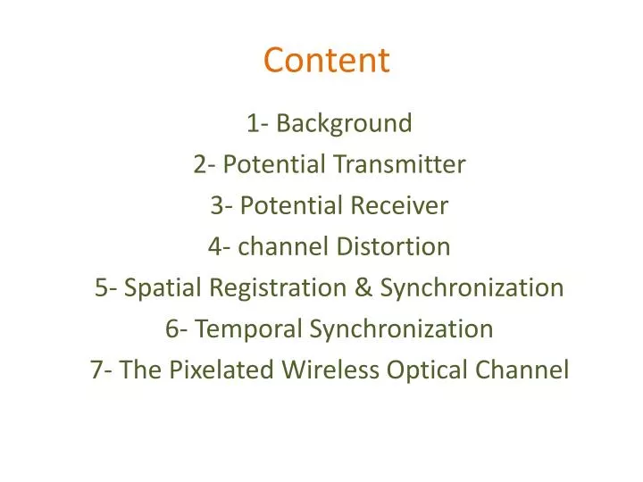
C ontent. 1- Background 2- Potential T ransmitter 3- Potential Receiver 4- channel D istortion 5- Spatial R egistration & Synchronization 6- Temporal S ynchronization 7- The Pixelated W ireless Optical C hannel. 1- Background.

E N D
Content 1- Background 2- Potential Transmitter 3- Potential Receiver 4- channel Distortion 5- Spatial Registration & Synchronization 6- Temporal Synchronization 7- The Pixelated Wireless Optical Channel
1- Background The MIMO wireless optical channel optical channel is a multi-element link which exploits spatial dimensions to achieve gains in reliability and spectral efficiency. The receiver is composed of a number of receive elements which detect the radiant optical power from a number of spatial mode. The transmitter, in the most general terms, is a spatial light modulator which produces an output optical intensity spatial distribution which is controlled by optical or electrical addressing. Some examples of these receivers, the point-to-point MIMO wireless optical channel differs from the holographic storage channel. The MIMO wireless optical systems considered here operate under incoherent illumination and are not affected by medium non-linearities as are holographic storage systems.
The primary noise source in MIMO wireless optical channels is due to ambient light sources and is signal dependent, whereas holographic storage suffers from inter-page cross-talk.Figure 1.1 presents an example of a point-to-point MIMO wireless optical channel. In this example, the transmitter produces a planar two-dimensional intensity wave front from an array of light emitting diodes. The point-to-point MIMO wireless optical channel topology can also be applied in a quasi-diffuse application as shown in Figure 1.2.
Point to point pixelated wireless optical channel A quasi diffuse pixelated wireless optical channel
2- Potential Transmitter The transmit spatial light modulator can be realized in a number of present day technologies. Liquid crystal display (LCD) panels have been used for some time in display applications. These devices modulate light through the electrical control of the polarization of a liquid crystal sandwiched between two oppositely oriented polarizer . Deformable mirror devices (DMD) are a new class of spatial light modulator. These devices fall into a wider class of devices known as micro-electromechanical (MEM) devices. They consist of an array of mirrors which can be deflected electro statically to modulate a constant light source. Organic polymer light emitting diodes (OLEDs) and electronic ink (E-INK) technologies allow flexible transmitters to be realized.
3- Potential Receiver The receiver is composed of an array of photo detective elements. The simplest implementation of such a structure can be accomplished by an array of photodiodes each with their own imaging optics . disadvantage of this approach is that relatively few receive elements can be used due to the cost and large size of the optical concentrators. 4- Channel Distortion Cathode ray tubes and LCD panels have a non-linear relationship between the input level to be transmitted and the optical intensity output. This non-linearity is commonly referred to as gamma distortion The distribution of this noise is typically taken as being Gaussian and signal dependent. In addition to this noise, quantization noise is also present due to the receive quantizer.
5- Spatial Registration & Synchronization In order to be able to detect the incoming images, the receiver must locatethe transmitted in the field-of-view. The process of determining the location ofan object in the field-of-view of a camera with respect to the camera coordinatesystem is known as registration. Registration is typically done with the aid of special calibration symbols, known as, which are known a priori at the receiver.
6- Temporal Synchronization In order to have a functional link, the receiver must be synchronized to the transmitter in time as well as in space. A simple technique to accomplish temporal synchronization is to transmit the frame clock as part of the transmitted image. Although this technique is simple to implement, it is an inefficient use of the transmit pixel. 7- the Pixelated wireless Optical Channel The pixel-matched MIMO wireless optical channel provides gains in spectral efficiency at the expense of requiring exact alignment between the transmit and receive elements. Furthermore, practical pixel-matched systems always suffer from some inter-channel interference and the number of pixels that can be used is typically limited by this interference.