Download
1 / 21
210 likes | 216 Vues
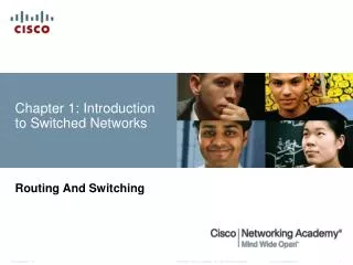
Chapter 2: Introduction to Switched Networks. Routing And Switching. 2.0. Chapter 2. 2.0 Introduction 2.1 Basic Switch Configuration 2.2 Switch Security: Management and Implementation. 2.0. Chapter 2: Objectives. Explain the advantages and disadvantages of static routing

E N D
Chapter 2: Introduction to Switched Networks Routing And Switching 2.0
Chapter 2 2.0 Introduction 2.1 Basic Switch Configuration 2.2 Switch Security: Management and Implementation 2.0
Chapter 2: Objectives • Explain the advantages and disadvantages of static routing • Configure initial settings on a Cisco switch • Configure switch ports to meet network requirements • Configure the management switch virtual interface • Describe basic security attacks in a switched environment • Describe security best practices in a switched environment • Configure the port security feature to restrict network access 2.0.1.1
Basic Switch ConfigurationSwitch Boot Sequence POST Run boot loader software Boot loader does low-level CPU initialization Boot loader initializes the flash filesystem Boot loader locates and loads a default IOS operating system software image into memory and hands control of the switch over to the IOS. 2.0.1.1
Basic Switch ConfigurationSwitch Boot Sequence • In order to find a suitable IOS image, the switch goes through the following steps: • It attempts to automatically boot by using information in the BOOT environment variable • If this variable is not set, the switch performs a top-to-bottom search through the flash file system. It will load and execute the first executable file, if it can. • The IOS operating system then initializes the interfaces using the Cisco IOS commands found in the configuration file, startup configuration, which is stored in NVRAM. Note: the command boot system can be used to set the BOOT environment variable. 2.1.1.1
Basic Switch ConfigurationRecovering From a System Crash • The boot loader can also be used to manage the switch if the IOS can’t be loaded. • The boot loader can be accessed through a console connection by: • Connect a PC by console cable to the switch console port. Unplug the switch power cord. • Reconnect the power cord to the switch and press and hold down the Mode button. • The System LED turns briefly amber and then solid green. Release the Mode button. • The boot loader switch:prompt appears in the terminal emulation software on the PC. 2.1.1.2
Basic Switch ConfigurationSwitch LED Indicators • Each port on Cisco Catalyst switches have status LED indicator lights. • By default these LED lights reflect port activity but they can also provide other information about the switch through the Mode button • The following modes are available on Cisco Catalyst 2960 switches: System LED Redundant Power System (RPS) LED Port Status LED Port Duplex LED Port Speed LED Power over Ethernet (PoE) Mode LED 2.1.1.3
Basic Switch ConfigurationSwitch LED Indicators • Cisco Catalyst 2960 switch modes 2.1.1.3
Basic Switch ConfigurationPreparing for Basic Switch Management • In order to remotely manage a Cisco switch, it needs to be configured to access the network • An IP address and a subnet mask must be configured • If managing the switch from a remote network, a default gateway must also be configured • The IP information (address, subnet mask, gateway) is to be assigned to a switch SVI (switch virtual interface) • Although these IP settings allow remote management and remote access to the switch, they do not allow the switch to route Layer 3 packets. 2.1.1.4
Basic Switch ConfigurationPreparing for Basic Switch Management Do the Buttons on 2.1.1.5 2.1.1.5
Configure Switch PortsConfigure Switch Ports at the Physical Layer Do the Buttons on 2.1.2.2 Students do button 2 2.1.2.2
Configure Switch PortsMDIX Auto Feature • Certain cable types (straight-through or crossover) were required when connecting devices • The automatic medium-dependent interface crossover (auto-MDIX) feature eliminates this problem • When auto-MDIX is enabled, the interface automatically detects and configures the connection appropriately • When using auto-MDIX on an interface, the interface speed and duplex must be set to auto Do the Buttons on 2.1.2.3 Students do button 3 2.1.2.3
Configure Switch PortsVerifying Switch Port Configuration Do the Buttons on 2.1.2.4 2.1.2.4
Configure Switch PortsNetwork Access Layer Issues Do the Buttons on 2.1.2.5 2.1.2.5
Configure Switch PortsNetwork Access Layer Issues • Troubleshooting Switch Media (connection) issues 2.1.2.6
Configure Switch PortsNetwork Access Layer Issues • Troubleshooting Interface-related issues 2.1.2.6