Download

1 / 21
210 likes | 345 Vues
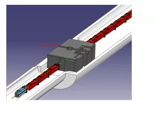
BI.BSW Chicane Magnets. D. Aguglia, J. Borburgh , B. Balhan, C. Baud, C. Bracco, C. C arli, M. Cieslak, M. Hourican, D. Nisbet, W. Weterings. Chicane layout. Beta beating mitigation. S-bend Only effective for a fixed angle, not throughout the ramp

E N D
BI.BSW Chicane Magnets D. Aguglia, J. Borburgh, B. Balhan, C. Baud, C. Bracco, C. Carli, M. Cieslak, M. Hourican, D. Nisbet, W. Weterings
Chicane layout Review on PSB 160 MeV H- injection
Beta beating mitigation • S-bend • Only effective for a fixed angle, not throughout the ramp • More difficult to implement mechanically, in particular on short magnets • Combined function magnets • Only effective for a fixed angle, not throughout the ramp • R-bend and active compensation • Chosen as baseline solution Review on PSB 160 MeV H- injection
Powering • Ramp down time ~ 5 ms. • Controlled ramp down to allow active compensation. • All four magnets per ring powered in series. • Each power converter will occupy either 2 or 3 19’’ standard racks. • 4 power converters + 1 spare = 10 to 15 racks. • Controllable switch mode power converter + current step-up transformer in the tunnel • Transformers to be placed near magnets, assuming 10μH margin (for cables + uncertainty on magnet inductance + transformer leakage inductance) → transformers must be placed not farther than ~5m from magnets! Review on PSB 160 MeV H- injection
Power converters Topology : AC/DC conversion to 1kVDC & DC/DC conversion via two interleaved IGBTs H-Bridges. Interleaved topology allows using standard IGBTs (current share) and reduces current ripple. Magnetic energy regenerated into the capacitor banks (minimized losses & power consumption) Power converter output: 1kV - 1.5kA 1.5MW peak power Simulated primary voltage and current
Bump closure flexibility • Following recommendation of “PS Booster with Linac4” review (January 2009), magnets are assumed to be powered in series per ring. →All magnets will have to provide same ∫B.dl/I. →Magnets should be aligned precisely at their position longitudinally. Would trim power supplies be desirable? Review on PSB 160 MeV H- injection
Space constraints • Magnets must be removable from ring without breaking vacuum. • Permissible septum thickness limited. • Longitudinal space limited to 380 mm, to allow sufficient space for stripping foil mechanism. • Magnetic length maximised (↘β beating). Review on PSB 160 MeV H- injection
Baseline magnet parameters Assumes ceramic vacuum chamber with a vertical beam acceptance ~ 65 mm. Review on PSB 160 MeV H- injection
Parameters per magnet type Review on PSB 160 MeV H- injection
How to describe field imperfections • What to calculate? • How to take into account field perturbations by dump and beam instrumentation? • Vacuum chamber coating neglected so far. • All calculations refer to By. Review on PSB 160 MeV H- injection Blue area within 1% of ∫Bnom.dl
How to take into account field imperfections • Static field imperfection can be described as dipole with higher orders, but these are position dependant during the ramp. • Influence of eddy currents could be neglected if sufficiently low (dump, vacuum chamber coating). • Field maps could be used, but would have to be calculated for each turn. • Imposing a maximum limit on the field imperfections (in space and time)? May lead to unrealistic values for such short magnets (magnetic length is less than 4 gap heights). Review on PSB 160 MeV H- injection
BSW1 leak field • Requirement not formalised. • Targeted leak field: 10-3∫Bnominal.dl. • External magnetic screen foreseen. • Count on injection steerers to compensate remaining leak field. Review on PSB 160 MeV H- injection
Influence of dump on field in BS4 • 2D and 3D simulations performed. • Both solid as well as segmented dumps evaluated. Field distortion by dump eddy currents Review on PSB 160 MeV H- injection
DUMP and its monitoring • BI equipment not taken into account for simulations as yet. • Dump specification defines a limit on the field disturbance due to presence of dump (1%). • Dump material suggested in specification: Carbon with resistivity in 1-510-5Ωm range. Review on PSB 160 MeV H- injection
Magnetic field on stripping foil • Forces induced on the foil not evaluated yet, but J and B rather low. • How to track electrons escaping from the foil? Jmod < 0.7 μA rose coloured Bmod < 6 mT rose coloured areas. Review on PSB 160 MeV H- injection
Mechanical integration (1/3) 2 turn coil, split-able magnets, outer dimensions, support development Interference with neighbouring equipment (BI, Stripping, Vacuum equipment).
Mechanical integration (2/3) • 2 turn coil, split-able magnets. • 0.35 mm thick laminations, glued magnets blocks. • Glued end plates, same material as yoke. • Is the use of glued laminated magnets a reliable over time? • Fixation to be studied. • Outer dimensions limited in height and length. • Magnet support and bus bars to be developed and integrated. • Transformers to be integrated in vicinity: dimensions to be evaluated, but rough estimation 80cmx80cmx80cm! • Interference with neighbouring equipment (BI, stripping foils, vacuum equipment). • Ease of maintenance required (RP ALARA)! Review on PSB 160 MeV H- injection
Mechanical integration (3/3) • Mechanical concept design started • Coil and yoke design to be completed at CERN • Coil and yoke manufacture to be subcontracted to industry • Mechanical support and installation jig to be designed and built in house Review on PSB 160 MeV H- injection
What if we adopt Inconel vacuum chambers? (1/2) + Mechanically more robust + Less costly + Potentially less activation Field deformation due to induced eddy currents: - delay (depending on vacuum chamber width) - deformed field shape Approximate field delays vary from 47μs (BSW1) to 90 μs (BSW4). Current distribution in race track shaped vacuum chamber. Review on PSB 160 MeV H- injection
What if we adopt Inconel vacuum chambers? (2/2) • Field quality deterioration. • Introduction of higher order field components, magnetic centre not on the central orbit. • Sextupolar components manageable, but quadrupolar component potentially dangerous (needs precise compensation to avoid resonance). • Field delay depends on width of vacuum chamber! • 3 field delays implies three power supplies per ring -> space for transformers (12!) ? • Try to design all magnets same gap and vacuum chamber width (inductance ↗, BS1 may become too tall or even more non-linear)? Review on PSB 160 MeV H- injection
Summary of outstanding questions • Would trim power supplies be recommended when powering all BSW per ring in series? • What to calculate to simulate the impact of field imperfections? • How to add the field deformation provoked by dump and its measurement systems? • Would imposing a limit on the absolute field imperfections (in space and time) be realistic? • Is septum (BSW1) leak field critical? • Is it necessary and how to track the electrons escaping from the stripping foil? • Are glued laminated yoke reliable over time in a radioactive environment? • What should be the preferred vacuum chamber material? • Have we overlooked anything else? Review on PSB 160 MeV H- injection