Optimizing Back-End Register Allocation in Compilers: Techniques and Strategies
This presentation covers the critical aspects of scalar register allocation in compilers, emphasizing the global register allocation problem and its resolution through graph coloring techniques. We explore the motivations behind effective register usage, including the need to minimize load/store operations by keeping values in registers longer. The presentation also reviews historical methods, such as the Chaitin coloring heuristic, and discusses current infrastructure needs for high-level compiler optimization, including interprocedural analysis and global optimization frameworks.


Optimizing Back-End Register Allocation in Compilers: Techniques and Strategies
E N D
Presentation Transcript
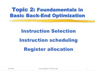
Topic 2b Basic Back-End Optimization Register allocation \course\cpeg421-10F\Topic-2b.ppt
Slides: Topic 3a Dragon book: chapter 10 S. Cooper: Chapter 13 Other papers as assigned in class or homework Reading List \course\cpeg421-10F\Topic-2b.ppt
Focus of This Topic • We focus on “scalar register allocation” • Local register is straightforward (read Cooper’s Section 13.3) • This global register allocation problem is essentially solved by graph coloring techniques: • Chaitin et. al. 1981, 82 (IBM) • Chow, Hennesy 1983 (Stanford) • Briggs, Kennedy 1992 (Rice) • Register allocation for array variables in loops -- subject not discussed here \course\cpeg421-10F\Topic-2b.ppt
High-Level Compiler Infrastructure Needed – A Modern View Front end Interprocedural Analysis and Optimization Good IR Loop Nest Optimization and Parallelization Global Optimization Code Generation \course\cpeg421-10F\Topic-2b.ppt
General Compiler Framework Source Inter-Procedural Optimization (IPO) • Good IPO • Good LNO • Good global optimization • Good integration of IPO/LNO/OPT • Smooth information passing between FE and CG • Complete and flexible support of inner-loop scheduling (SWP), instruction scheduling and register allocation Loop Nest Optimization (LNO) Global Optimization (OPT) ME Global inst scheduling Innermost Loop scheduling Arch Models Reg alloc Local inst scheduling CG Executable \course\cpeg421-10F\Topic-2b.ppt
RISC VLIW/SuperScalar EPIC/MP CMP/MT 1980 1985 1990 1995 2000 2005 2010 A Map of Modern Compiler Platforms GNU Compilers IMPACT Compiler HP Research Compiler Trimaran Compiler Cydra VLIW Compiler SGI Pro Compiler - Designed for ILP/MP - Production quality - Open Source Open64 Compiler (PathScale, ORC, Osprey) Multiflow VLIW Compiler LLVM Compiler Ucode Compiler Chow/Hennessy SUIF Compiler \course\cpeg421-10F\Topic-2b.ppt
Osprey Compiler Performance (4/3/07) Curtesy: S.M. Liu (HP) • GCC4.3 at –O3 • With additional options recommended by GCC developers • Two programs has runtime error using additional options • Osprey3.1 with vanilla –O3 • The performance delta is ~10%, excluding two failing programs \course\cpeg421-10F\Topic-2b.ppt
Vision and Status of Open64 Today ? • People should view it as GCC with an alternative backend with great potential to reclaim the best compiler in the world • The technology incorporated all top compiler optimization research in 90's • It has regain momentum in the last three years due to Pathscale, HP and AMD’s (and others) investment in robustness and performance • Targeted to x86, Itanium in the public repository, ARM, MIPS, PowerPC, and several other signal processing CPU in private branches \course\cpeg421-10F\Topic-2b.ppt
Register Allocation • Motivation • Live ranges and interference graphs • Problem formulation • Solution methods \course\cpeg421-10F\Topic-2b.ppt
Motivation • Registers much faster than memory • Limited number of physical registers • Keep values in registers as long as possible (minimize number of load/stores executed) \course\cpeg421-10F\Topic-2b.ppt
Goals of Optimized Register Allocation 1 Pay careful attention to allocating registers to variables that are more profitable to reside in registers 2 Use the same register for multiple variables when legal to do so \course\cpeg421-10F\Topic-2b.ppt
Brief History of Register Allocation Chaitin: Coloring Heuristic. Use the simple stack heuristic for ACM register allocation. Spill/no-spill SIGPLAN decisions are made during the Notices stack construction phase of the 1982 algorithm Briggs: Finds out that Chaitin’s algorithm PLDI spills even when there are available 1989 registers. Solution: the optimistic approach: may-spill during stack construction, decide at spilling time. \course\cpeg421-10F\Topic-2b.ppt
Brief History of Register Allocation (Con’t) Chow-Hennessy: Priority-based coloring. SIGPLAN Integrate spilling decisions in the 1984 coloring decisions: spill a variable ASPLOS for a limited life range. 1990 Favor dense over sparse use regions. Consider parameter passing convention. Callahan: Hierarchical Coloring Graph, PLDI register preference, 1991 profitability of spilling. \course\cpeg421-10F\Topic-2b.ppt
Assigning Registers to more Profitable Variables (example) c = ‘S’ ; sum = 0 ; i = 1 ; while ( i <= 100 ) { sum = sum + i ; i = i + 1 ; } square = sum * sum; print c, sum, square; Source code fragment: \course\cpeg421-10F\Topic-2b.ppt
The Control Flow Graph of the Example [100] c = ‘S’ [101] sum := 0 [102] i := 1 c = ‘S’ ; sum = 0 ; i = 1 ; while ( i <= 100 ) { sum = sum + i ; i = i + 1 ; } square = sum * sum; print c, sum, square; [103] label L1: [104] if i > 100 goto L2 false true [105] sum := sum + i [106] i := i + 1 [107] goto L1 [108] label L2: [109] square = sum * sum [110] print c, sum, square \course\cpeg421-10F\Topic-2b.ppt
Desired Register Allocation for Example Assume that there are only two non-reserved registers available for allocation ($t2 and $t3). A desired register allocation for the above example is as follows: c = ‘S’ ; sum = 0 ; i = 1 ; while ( i <= 100 ) { sum = sum + i ; i = i + 1 ; } square = sum * sum; print c, sum, square; Variable Register c no register sum $t2 i $t3 square $t3 \course\cpeg421-10F\Topic-2b.ppt
1. Pay careful attention to assigning registers to variables that are more profitable The number ofdefs(writes) and uses(reads) to the variables in this sample program is as follows: Register Allocation Goals c = ‘S’ ; sum = 0 ; i = 1 ; while ( i <= 100 ) { sum = sum + i ; i = i + 1 ; } square = sum * sum; print c, sum, square; Variable #def’s #use’s c 1 1 sum 101 103 i 101 301 square 1 1 variables sum and i should get priority over variable c for register assignment. \course\cpeg421-10F\Topic-2b.ppt
2. Use the same register for multiple variables when legal to do so Reuse same register ($t3) for variables I and square since there is no point in the program where both variables are simultaneously live. Register Allocation Goals c = ‘S’ ; sum = 0 ; i = 1 ; while ( i <= 100 ) { sum = sum + i ; i = i + 1 ; } square = sum * sum; print c, sum, square; Variable Register c no register sum $t2 i $t3 square $t3 \course\cpeg421-10F\Topic-2b.ppt
Register Allocation vs. Register Assignment Register Allocation – determining which values should be kept in registers. It ensures that the code will fit the target machine’s register set at each instruction. Register Assignment – how to assign the allocated variables to physical registers. It produces the actual register names required by the executable code. \course\cpeg421-10F\Topic-2b.ppt
Local and Global Register Allocation • Local register allocation (within a basic block): algorithms are generally straightforward – but implementation needs care [Cooper: 13.3] • Gloabal register allocation – graph coloring method \course\cpeg421-10F\Topic-2b.ppt
Liveness Intuitively a variable v is live if it holds a value that may be needed in the future. In other words, v is live at a point pi if: (i) v has been defined in a statement that precedes pi in any path, and (ii) v may be used by a statement sj, and there is a path from pito sj.. (iii) v is not killed between pi and sj. \course\cpeg421-10F\Topic-2b.ppt
s1 s2 a: s1 = ld(x) b: s2 = s1 + 4 c: s3 = s1 8 d: s4 = s1 - 4 e: s5 = s1/2 f: s6 = s2 * s3 g: s7 = s4 - s5 h: s8 = s6 * s7 Live Variables A variable v is live between the point pi that succeeds its definition and the point pj that succeeds its last use. The interval [pi, pj] is the live range of the variable v. Which variables have the longest live range in the example? Variables s1 and s2 have a live range of four statements. \course\cpeg421-10F\Topic-2b.ppt
a: s1 = ld(x) b: s2 = s1 + 4 c: s3 = s1 8 d: s4 = s1 - 4 e: s5 = s1/2 f: s6 = s2 * s3 g: s7 = s4 - s5 h: s8 = s6 * s7 Register Allocation How can we find out what is the minimum number of registers required by this basic block to avoid spilling values to memory? We have to compute the live range of all variables and find the “fatest” statement (program point). Which program points have the most variables that are live simultaneously? \course\cpeg421-10F\Topic-2b.ppt
s1 s2 s3 a: s1 = ld(x) s4 b: s2 = s1 + 4 s5 c: s3 = s1 8 s6 d: s4 = s1 - 4 s7 e: s5 = s1/2 f: s6 = s2 * s3 g: s7 = s4 - s5 h: s8 = s6 * s7 Register Allocation At statement e variables s1, s2, s3, and s4 are live, and during statement f variables s2, s3, s4, and s5 are live. But we have to use some math: our choice is liveness analysis. \course\cpeg421-10F\Topic-2b.ppt
s1 s2 s3 a: s1 = ld(x) s4 b: s2 = s1 + 4 s5 c: s3 = s1 8 s6 d: s4 = s1 - 4 s7 e: s5 = s1/2 f: s6 = s2 * s3 g: s7 = s4 - s5 h: s8 = s6 * s7 Live-in and Live-out live-in(r): set of variables that are live at the point that immediately precedes statement r. live-out(r): set of variables variables that are live at the point that immediately succeeds r. \course\cpeg421-10F\Topic-2b.ppt
s1 s2 s3 a: s1 = ld(x) s4 b: s2 = s1 + 4 s5 c: s3 = s1 8 s6 d: s4 = s1 - 4 s7 e: s5 = s1/2 f: s6 = s2 * s3 g: s7 = s4 - s5 h: s8 = s6 * s7 Live-in and Live-out: Program Example What are live-in(e) and live-out(e)? live-in(e) = {s1,s2, s3, s4} live-out(e) = {s2, s3, s4, s5} \course\cpeg421-10F\Topic-2b.ppt
Live-in and Live-out in Control Flow Graphs live-in(B): set of variables that are live at the point that immediately precedes the first statement of the basic block B. live-out(B): set of variables that are live at the point that immediately succeeds the last statement of the basic block B. \course\cpeg421-10F\Topic-2b.ppt
Live-in and Live-out of basic blocks • live-in(B1)={b,c,d,f} • live-in(B2)={a,c,d,e} • live-in(B3)={a,c,d,f} • live-in(B4)={c,d,f} B1 a := b + c d := d - b e := a + f • live-out(B1)={a,c,d,e,f} • live-out(B2)={c,d,e,f} • live-out(B3)={b,c,d,e,f} • live-out(B4)={b,c,d,e,f} B2 B3 f := a - d b := d + f e := a - c B4 b := d + c b, d, e, f live b, c, d, e, f live \course\cpeg421-10F\Topic-2b.ppt (Aho-Sethi-Ullman, pp. 544)
Register-Interference Graph A register-interference graph is an undirected graph that summarizes live analysis at the variable level as follows: • A node is a variable/temporary that is a candidate for register allocation (exceptions are volatile variables and aliased variables) • An edge connects nodes V1 and V2 if there is some program point in the program where variables V1 and V2 are live simultaneously. (Variables V1 and V2 are said to interfere, in this case). \course\cpeg421-10F\Topic-2b.ppt
s1 s2 s3 a: s1 = ld(x) s4 b: s2 = s1 + 4 s5 c: s3 = s1 8 s6 d: s4 = s1 - 4 s7 e: s5 = s1/2 f: s6 = s2 * s3 g: s7 = s4 - s5 h: s8 = s6 * s7 Register Interference Graph: Program Example s1 s7 s2 s3 s6 s4 s5 \course\cpeg421-10F\Topic-2b.ppt
Local Register Allocation vs. Global Register Allocation • Local Register Allocation (basic block level) • Allocate for a single basic block - using liveness information • generally straightforward • may not need graph coloring • Global Register Allocation (CFG) • Allocate among basic blocks • graph coloring method • Need to use global liveness information \course\cpeg421-10F\Topic-2b.ppt
Register Allocation by Graph Coloring Background: A graph is said to be k-colored if each node has been assigned one of k colors in such a way that no two adjacent nodes have the same color. Basic idea: A k-coloring of the interference graph can be directly mapped to a legal register allocation by mapping each color to a distinct register. The coloring property ensures that no two variables that interfere with each other are assigned the same register. \course\cpeg421-10F\Topic-2b.ppt
The basic idea behind register allocation by graph coloring is to 1. Build the register interference graph, 2. Attempt to find a k-coloring for the interference graph. Register Allocation by Graph Coloring \course\cpeg421-10F\Topic-2b.ppt
The problem of determining if an undirected graph is k-colorable is NP-hard for k >= 3. It is also hard to find approximate solutions to the graph coloring problem Complexity of the Graph Coloring Problem \course\cpeg421-10F\Topic-2b.ppt
Question: What to do if a register-interference graph is not k-colorable? Or if the compiler cannot efficiently find a k-coloring even if the graph is k-colorable? Answer: Repeatedly select less profitable variables for “spilling” (i.e. not to be assigned to registers) and remove them from the interference graph till the graph becomes k-colorable. Register Allocation \course\cpeg421-10F\Topic-2b.ppt
Estimating Register Profitability The register profitabil ity of variable v is estimated by : å = ´ profitabil ity(v) freq(i) savings(v , i) i freq(i) : estimated execution frequency of basic block i (obtained by profiling or by static analysis), savings (v , i) : estimated number of processor cycles that wo uld be saved due to a reduced number of load and store instructio ns in basic block i , if a register w as assigned to variable v . \course\cpeg421-10F\Topic-2b.ppt
Example of Estimating Register Profitability Basic block frequencies for previous example: B freq(B) [100] 1 [101] 1 [102] 1 [103] 101 [104] 101 [105] 100 [106] 100 [107] 100 [108] 1 [109] 1 [110] 1 \course\cpeg421-10F\Topic-2b.ppt
Estimation of Profitability (Assume that load and store instructions take 1 cycle each on the target processor) Profitability(c) = freq ([100]) * (1 - 0) + freq([110]) * (1 - 0) = 2 Profitability(sum)= freq ([101]) * (1 - 0) + freq([105]) * (2 - 0) + freq([109]) * (2 - 0) = 1 * 1 + 100 * 2 + 1 * 2 = 203 Profitability(i) = freq ([102]) * (1 - 0) + freq([104]) * (1 - 0) + freq([105]) * (1 - 0) + freq([106]) * (2 - 0) = 1 * 1 + 101 * 1 + 100 * 1 + 100 * 2 = 402 Profitability = freq ([109]) * (1 - 0) + freq([110]) * (1 - 0) (square) = 2 \course\cpeg421-10F\Topic-2b.ppt
Heuristic Solutions Key observation: GG’ . Remove a node x with degree < k From G, and all associated edges What do we know about k-colorability of G if we know G’ is k-colorable ? Answer: If G’ is k-colorable => So is G! Why ? \course\cpeg421-10F\Topic-2b.ppt
A 2-Phase Register Allocation Algorithm Select and Spill Build IG Simplify Reverse pass Forward pass \course\cpeg421-10F\Topic-2b.ppt
Heuristic “Optimistic”Algorithm /* Build step */ Build the register-interference graph, G; /* Forward pass */ Initialize an empty stack; repeat while G has a node v such that |neighbor(v)| < kdo /* Simplify step */ Push (v, no-spill) Delete v and its edges from G end while if G is non-empty then /* Spill step */ Choose “least profitable” node v as a potential spill node; Push (v, may-spill) Deletev and its edges from G end if until G is an empty graph; \course\cpeg421-10F\Topic-2b.ppt
Heuristic “Optimistic”Algorithm /* Reverse Pass */ whilethe stack is non-emptydo Pop(v, tag) N := set of nodes in neighbors(v); if(tag = no-spill)then /* Select step */ Select a register R for v such that R is not assigned to nodes in N; Insert v as a new node in G; Insert an edge in G from v to each node in N; else /* tag = may-spill */ ifv can be assigned a register R such that R is not assigned to nodes in Nthen /* Optimism paid off: need not spill */ Assignregister R to v; Insertvas a new node in G; Insertan edge in G from v to each node in N; else /* Need to spill v */ Mark v as not being allocate a register end if end if end while \course\cpeg421-10F\Topic-2b.ppt
The above register allocation algorithm based on graph coloring is both efficient (linear time) and effective. It has been used in many industry-strength compilers to obtain significant improvements over simpler register allocation heuristics. Remarks \course\cpeg421-10F\Topic-2b.ppt
Extensions • Coalescing • Live range splitting \course\cpeg421-10F\Topic-2b.ppt
In the sequence of intermediate level instructions with a copy statement below, assume that registers are allocated to both variables x and y. Coalescing There is an opportunity for further optimization byeliminating the copy statement if x and y are assigned the same register. x := … . . . y := x . . . … := y The constraint that x and y receive the same register can be modeled bycoalescing the nodes forx and yin the interference graph i.e., by treating them as the same variable. \course\cpeg421-10F\Topic-2b.ppt
An Extension with Coalesce Build IG Simplify Coalesce Select and Spill \course\cpeg421-10F\Topic-2b.ppt
Register Allocation with Coalescing 1. Build: build the register interference graph G and categorize nodes as move-related or non-move-related. 2. Simplify: one at a time, remove non-move-related nodes of low (< K) degree from G. 3. Coalesce: conservatively coalesce G: only coalesce nodes a and b if the resulting a-b node has less than K neighbors. 4. Freeze: If neither coalesce nor simplify works, freeze a move-related node of low degree, making it non-move-related and available for simplify. \course\cpeg421-10F\Topic-2b.ppt (Appel, pp. 240)
actual spill potential spill select (re)build simplify coalesce freeze Register Allocation with Coalescing 5. Spill: if there are no low-degree nodes, select a node for potential spilling. 6. Select: pop each element of the stack assigning colors. \course\cpeg421-10F\Topic-2b.ppt (Appel, pp. 240)
k j LIVE-IN: k j g g := mem[j+12] h h := k -1 f f := g + h e e := mem[j+8] m m := mem[j+16] b b := mem[f] c c := e + 8 d d := c k := m + 4 j := b LIVE-OUT: d k j Example:Step 1: Compute Live Ranges \course\cpeg421-10F\Topic-2b.ppt
Example:Step 3: Simplify (K=4) f e stack j k b m (h,no-spill) d c h g \course\cpeg421-10F\Topic-2b.ppt (Appel, pp. 237)