Download

1 / 42
440 likes | 477 Vues
Manufacturing Processes. Chap. 22 -Machining of Round Shapes. Machining of Round Shapes. The following operations are typically done on a lathe. Selection of the machine tool will depending on: desired surface finish required dimensional tolerances

E N D
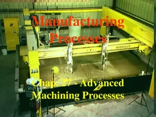
Manufacturing Processes Chap. 22 -Machining of Round Shapes
Machining of Round Shapes • The following operations are typically done on a lathe. • Selection of the machine tool will depending on: • desired surface finish • required dimensional tolerances • Cutting parameters will also vary with the operation.
Machining of Round Shapes • Turning • To produce a straight, conical, curved or grooved workpiece. • Facing • Produce a flat surface at the end of a part. • Forming • To produce various shapes and profiles. • Drilling • To produce a hole.
Machining of Round Shapes • Boring • To enlarge holes/cylindrical cavities made by a previous process or to produce internal grooves. • Parting • To cut off the end of a part for production of discrete parts. • Knurling • To generate a regular-shaped roughness on cylindrical surfaces. • Threading • Production of internal / external threads.
1. Turning • Most lathe work is turning. • Involves the use of simple single-point cutting tools. • Primary motion is rotational; tool feeds parallel to rotation axis. • Parameters: N (rpm), V (surf. ft/min), fr (in/rev). • Depth of Cut = D1 –D2 / 2
Turning Practice • Usual procedure for good finish & accuracy: • Perform several roughing cuts at high feed rates and large d.o.c.’s. • Use larger d.o.c. and smaller feed rather than the inverse to improve efficiency. • Then do finishing cuts, with lower feed and depth of cut for a good surface finish. (usually less than 0.015”). • For good finish & accuracy • Start with one + roughing cuts. • Finishing cuts follow • Always use some type of cutting fluid: (an emulsion, fatty oil, mineral oil, or using synthetic fluid.)
Cutting Forces in Turning • Recall that there are three main forces acting in turning: • Cutting Force Fc • acts downward on the tip of the tool. • tends to deflect tool downward. • supplies energy for the cutting operation. • Thrust Force Ft • acts in longitudinal direction (feed direction) • Radial Force Fr • acts in radial direction (feed direction) • tends to push tool away from workpiece.
Turning Practices • Depending on the material being cut and operation, you can check a corresponding table for recommended cutting tool material, and cutting parameters. • This is a general recommendation and should be used as a starting point. • See table 21-1 for example.
Turning Formulas • Once cutting speed, feed and d.o.c. are selected based on workpiece & cutting tool materials: • Select the machine RPM (N) • N = 12 V / P D1 • Cutting Time will be • CT = L + A / fr N L = length of the cut, A is distance allowance.
Turning Formulas • MRR = Volume removed per unit time, is • MRR = [12 V fr d (D12 – D22)] / 4 D1 or • MRR ~ 12 V fr d (in3 /min) • assumes d.o.c. << D1 • Torque T = (Fc) ( Davg / 2) (ft-lb) • Power P = Torque () where = 2N rads/min.
2. Boring • Always involves enlarging an existing hole • (created by drilling or result of casting core). • Usually done to make sure a hole is concentric with the axis of rotation of workpiece. • In essence, it is internal turning. • Tools have larger clearance angles to avoid subbing. • Possibility of vibration and chatter is increased , so d.o.c.s have to be less.
Boring Formulas • MRR = Volume removed per unit time, is • MRR = [ L( D12 – D22) / 4 ] / [L / fr N ] (in3 /min) • D2 is original hole diameter, L is length of cut along the axis. • Cutting Time will be • CT = L + A / fr N L = length of the cut, A is distance allowance.
3. Facing • Making a flat surface by feeding the tool along the end of the rotating workpiece. • Must set up tool at the exact center of rotation. • If both ends of a piece are to be faced, need to do one side first, then the other. • Can use a mandrel to do in one setup, if part geometry permits. • Since tool feeds perpendicular to the axis of rotation, • Speed is always decreasing as tool moves. • Compute speed using largest diameter.
Facing Formulas • MRR = Volume removed per unit time, is • MRR = [ D2 L1 N ] / 4 L = 6 fr L1 (in3 /min) • L1 = d.o.c. and L = D / 2 = length of the cut. • Cutting Time will be • CT = L + A / fr N [ D/2 + A ] / fr N • L = length of the cut, A is distance allowance.
4. Parting • The severing of a workpiece from the remainder by means of a cutoff tool. • Cutoff tools are thin and have large overhang, • They are difficult to manage. • Must line up at the exact height of the angle of rotation. • Usually machine at lower speeds and feeds because of overhang. • Formulas: • L = D/2 (solid bars) • CT and MRR formulas are the same as for facing.
5. Drilling • Performed by mounting a drill bit into a drill chuck inside the tailstock quill. • Workpiece is placed in a workholder on headstock • Quill is advanced by rotating hand wheel.
Other Lathe Operations • Forming, • Grooving • Knurling • Thread Cutting. • Done with specially shaped tools or with inserts.
The Lathe • One of the oldest machine tools. • Originally called an engine lathe (operated by overhead pulleys & belts). • Engine lathe requires a skilled machinist: all controls are hand operated. • Inefficient for repetitive jobs / large runs. • Other types include toolroom lathes (high precision) special purpose lathes (for gun barrels, special applications).
Lathe Components (See Fig. 23.10) • Bed: Supports all major components • Headstock: has motors, pulleys, V-belts that supply power to spindle. • Tailstock: Can slide along ways. Equipped with a center, (dead when fixed or live when rotating). • Carriage: Assembly that consists of cross-slide, tool post & apron • Gearbox: connects feed rod and leadscrew • Leadscrew: used for controlled motion i.e. to cut threads. • Feed Rod: Connected to headstock. Tears make rotation possible and provides movement to carriage and cross-slide.
Lathe Components • Spindle: rotational element in lathe. Can attach chucks or collets to hold work. • Quill: Location for mounting tools on tailstock. • Ways: Guide rails over which the carriage slides. • Tool post: Mounting fixture for tool. • Compound rest: Swivel for tool positioning / adjusting. • Cross-Slide: Moves radially in and out, used for facing. • Apron: Provides guiding mechanism over lead screw / feed rod.
Lathe Specifications • Lathe Specifications: • Swing • ~ 2 times the distance between the lathe centers and nearest point on the ways. • Indicates max. diameter of workpiece that can be machined. • Max Distance between centers • Distance between headstock and tailstock. • Indicates max. length that can be mounted between centers.
Turning Equipment • Engine Lathes • Most frequently used • 12 – 24” swing, 24 - 48” center distances. • 50” Swing / 12 ft. center distances not uncommon. • Very versatile. • Long times required for setup, changing tools. • Requires operator’s full attention. • Turret Lathes • A hexagon turret replaces the tailstock. • 6 Tools can be mounted on turret. • Turret is rotated to locate tool to proper cutting position. • Turret can be fed parallel to the ways or transversely. • Saves time in workpiece setup, tool changing.
Turning Equipment • Turret Lathes • Vertical / Horizontal • For large / heavy parts • (rings, pinions, other) • Automatic • Simple machine • Low /no operator skill required.
Turning Equipment • Single Spindle Automatic Screw Machines Originally designed for small parts like bolts & screws, hence the name. • Turret Type (Brown & Sharpe) Screw Machine • Small automatic turret lathe • Designed for bar stock. • All motions controlled by cams. • Have bar feeding mechanism for better efficiency. • Swiss Type Screw Machine • Similar in that cams control motion. • Very good machines for small parts.
Turning Equipment • Multiple Spindle Automatic Screw Machines • Have between 4 and 8 spindles. • All tools cut simultaneously. • Spindles are set on indexable drum. • Tools are feed longitudinally. • Requires only that bar stock feed rack be supplied.
Boring Equipment • Vertical Boring and Turning Machine • Essentially the same as a vertical turret lathe. • Has two main toolheads rather than 1 turret. • 30 - 40’ in diameter. • Jig Borer • A very precise vertical boring machine. • Used to make jigs and fixtures, hence the name. • Horizontal Boring (Drilling & Milling) Machine • Very useful for large parts.
Tools for Lathes • Cutting tools must be rigidly supported to minimize deflection and vibration. • Several types exist. • Right hand and left hand turning tools • Right hand and left hand facing tools. • Round and Broad nose turning tools • Cut-off tools. • Threading tools • Forming, knurling. • Insert tools.
Work Holding Devices • Chucks • 3 or 4 Jaw types • Can be power actuated or manual. • 3-Jaw chucks are self centering with a gear. • Used for round workpieces. • Can center to 0.001” • 4-Jaw chuck jaws can be independently moved. • Can be used for square, rectangular or odd shaped pieces. • Used for heavy pieces / where concentricity is critical.
Work Holding Devices • Chucks
Work Holding Devices • Collets • A longitudinally-split tapered bushing. • Workpiece is placed inside collet. • Collet is pulled into spindle electronically. • Tapers push in, tightening workpiece. • Better grip of workpiece than with a collet. • Typically max.. diameter of workpiece is 1” with a collet.
Work Holding Devices • Face plates • Used for clamping irregularly shaped workpieces. • Mandrels • Placed inside hollow/tube pieces to hold them. • Used when fixturing on both ends is required.
Process Capabilities in Turning • Machining is a slow process in itself. • Other processes must be considered before bringing machining into the picture. • Economics play major role in decision. • Production Rates • Engine Lathe Very Low-Low • Turret Lathe Low to Medium • CNC Lathe Low to Medium • Multiple Spindle Chuckers High to Very High
Process Capabilities in Turning • Surface Finish & Dimensional Accuracy • Result of several factors: • Machine tool conditions • Process parameters • Tool geometry/wear • Cutting fluid use • Machinability • Operator skill, among others. • Average Turning Surface Finish Range: 250 – 16 min. • Average Turning Tolerance Range: 0.020” – 0.040”
Design Considerations in Turning • When designing a turned component, you must consider economics. • Consider the following guidelines. • Design part so it can be easily fixtured /clamped. (Long, thin parts have problems withstanding cutting and clamping forces). • Allow dimensional tolerances & surface finish to be as wide as possible.
Design Considerations in Turning • Avoid sharp corners, tapers, major dimensional changes. • Machine blanks as close to final dimensions as possible to reduce time. • Design parts without obstructions to the cutting tool. • Design for standard tooling. • Select machinable materials.
Turning Considerations • Minimize tool overhang. • Support workpiece rigidly. • Use machine tools with high stiffness/damping capacity. • If vibrations/ chatter occur, modify cutting parameters, tool geometry, or use cutting fluid. • Refer to Table 22.9 for Turning Troubleshooting (*)
Thread Cutting • Threads are an important machine element. • Definition: “A ridge of uniform cross-section that follows a helical or spiral path on the inside or outside of a cylindrical or tapered surface.” • Can be right or left handed.
Thread Cutting • Typically produced by: • Forming (when large quantities of threaded parts are required). • Cutting. • Casting (with loss of dimensional accuracy / surface finish). • Threading: cutting of threads on a lathe. • Tapping: when cutting internal threads with a special threaded tool. • External threads: typically cut with a die.
Screw Thread Cutting on a Lathe • Threads are deep, coarse feed marks. • Cutting tool depends on type of thread being cut. • Tool is mounted on holder that moves along workpiece by leadscrew. • Slower motion yields finer thread. • Need several passes to produce good thread accuracy.
Thread Nomenclature • See (Fig. 22.16) • American National Thread System (Unified System): US, Canada, UK. ½ - 20 UNF - 2 - A a b c d e • a: Nominal Size (Major diameter) • b: TPI • c: Thread Series • d: Thread Class • e: External/Internal Thread
Thread Nomenclature • ISO General Purpose Screw Thread Form (more universal standard) M 6 x 0.75 - 5 g 6 g a b c d e f g • a: Metric Thread • b: Nominal Size (mm) • c: Thread Pitch • d: Tolerance Grade of Pitch Diameter • e: Tolerance Position of Pitch Diameter • f: Tolerance Grade of Crest Diameter • g: Tolerance Position of Crest Diameter