Download
1 / 11
110 likes | 219 Vues
Thoughts on the Lidar Operating Point for the Upcoming NexGen NPOESS Wind Mission Instrument Design at GSFC Michael J. Kavaya NASA Langley Research Center michael.j.kavaya@nasa.gov Working Group on Space-Based Lidar Winds Monterey, California USA 5 – 8 February 2008.

E N D
Thoughts on the Lidar Operating Point for the Upcoming NexGen NPOESS Wind Mission Instrument Design at GSFCMichael J. KavayaNASA Langley Research Centermichael.j.kavaya@nasa.govWorking Group on Space-Based Lidar WindsMonterey, California USA5 – 8 February 2008
NASA’s instrument and mission hybrid Doppler wind lidar (HDWL) Global Wind Observing Sounder (GWOS) study took place at GSFC in September and October 2006 • The study assumed a 400 km orbit height, a 45 degree lidar nadir angle, and the Global Tropospheric Wind Sounder (GTWS) “Demonstration” wind measurement requirements (added in 2006 with NASA HQ and GTWS SDT approval; now hopefully renamed the 2008 NASA/NOAA “Science Demonstration” requirements) • The GWOS study team cleverly solved the large moving lidar scanner problem with four fixed 50-cm diameter telescopes to obtain 2 lines of vector wind profiles • The GWOS study lidar operating points were: CDWL at 0.25 J pulse energy and 5 Hz; DDWL at 0.8/0.36 J and 100 Hz • The NRC Earth Science Decadal Survey endorsed the HDWL mission in January 2007 • The NPOESS/IPO planned spacecraft orbit height is 824 km, and winds is their #1 unaccommodated measurement • NPOESS/IPO/Dr. Stephen A. Mango has funded an instrument study at GSFC for an HDWL mission at 824 km. The study is scheduled for 25 – 29 Feb. 2008. • The best use of 1 week of the GSFC IDC team is to narrow down the lidar operating points before the study begins History and Motivation
Geometry400 vs. 824 km45 degree nadir angleSpherical earth 400 – 48.5 s/350 km 824 – 53.1 s/350 km
Connecting Lidar Parameters to Measurement Performance Coherent Detection Doppler Wind Lidar • Equal Performance Parameter Linkages: • Note: better vertical resolution is a smaller value of “Vert Res” • If decrease (improve) Vert Res by a factor F, then increase E by a factor , or increase PRF by F, or increase D by • If increase number of azimuth angles NAZ by a factor F, then increase PRF by F, or increase Vert Res by F, or increase E by , or increase D by • If increase R by a factor F, then increase D by F, or increase E by F2, or increase PRF or Vert Res by F4
Connecting Lidar Parameters to Measurement Performance Direct Detection Doppler Wind Lidar • Equal Performance Parameter Linkages: • If decrease (improve) “Vert Res” by a factor F, then increase E or PRF by F, or increase D by • If increase number of azimuth angles NAZ by a factor F, then increase PRF or Vert Res or E by F, or increase D by • If increase R by a factor F, then increase D by F, or increase E or PRF or Vert Res by F2
NWOS Mission StudyThoughts on Lidar Parameter Strategy • From geometry only, going from 400 km to 824 km, the increase in range is effectively a factor of 2.16 (assuming 45 deg. nadir and spherical earth). We consider restoring the original lidar velocity measurement performance with either changes in only pulse energy, or only PRF, or only optical diameter: • The vertical resolution requirement for operational is x 2 smaller (harder) than for science demonstration: • The number of azimuth angles for operational is x 2 greater than for science demonstration:
NWOS Mission StudyThoughts on Lidar Parameter Strategy • Combining Tables 2 and 3 to see the total effect of operational vs. science demonstration requirements, neglecting time to advance by horizontal resolution (10% effect): • Combining Tables 1 and 4 to see the total effect of higher orbit height and operational requirements: • Comparing Table 1 with Table 5, it seems prudent to perform the NWOS Mission Study using the same Science Demonstration requirements as were used in GWOS. We assume this choice below (Table 1)
NWOS Mission StudyThoughts on Lidar Parameter Strategy • Using the factors in Table 1 and the original GWOS mission parameters, we get the actual values of the parameters:
NWOS Mission StudyThoughts on Lidar Parameter Strategy • The laser’s required input power and heat removal are proportional to the product of the energy and PRF. This was dominated by the direct lidar in GWOS. • The laser’s mission lifetime is inversely proportional to PRF (not counting PRF effect on energy) • The laser’s mission lifetime decreases as pulse energy increases (not counting E effect on PRF) • The data rate is proportional to PRF. This was dominated by the coherent lidar in GWOS. • For the coherent lidar, it is very attractive to stay at 50 cm and let the pulse energy and PRF rise. A pulse energy of 1.2 J at 2 Hz has been demonstrated at LaRC. A possible NWOS operating point for coherent would be 1.2 J at 5 Hz. • The direct lidar, with 50 cm, must increase the average laser power by a factor of 4.7 somewhere between the extremes of 3.76 J at 100 Hz, and 0.8 J at 470 Hz. Perhaps this eliminates 50 cm for the direct lidar. • A possible NWOS operating point for direct would be 1000/450 mJ, 190 Hz, and 0.7 m. Coherent may not use the entire 0.7 m, but only the center of the mirror.
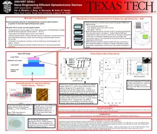
NWOSScience Demonstration Requirements EXAMPLE COHERENT OPTIONS 1.2 J 5 Hz 6 W 0.5 m EXAMPLE DIRECT OPTIONS 3.76 J (1.69) 100 Hz 376 W 0.5 m 0.8 J (0.36) 470 Hz 376 W 0.5 m 1.0 J (0.45) 190 Hz 190 W 0.7 m 1.2 J (0.54) 158 Hz 190 W 0.7 m 1.4 J (0.63) 135 Hz 190 W 0.7 m