Download
1 / 28
280 likes | 418 Vues
Plans for DC Readout Experiment at the 40m Lab. Alan Weinstein for the 40m Lab July 19, 2005. Ben Abbott, Rana Adhikari, Dan Busby, Jay Heefner, Keita Kawabe, Osamu Miyakawa, Virginio Sannibale, Mike Smith, Kentaro Somiya, Monica Varvella, Steve Vass, Rob Ward, Alan Weinstein.

E N D
Plans for DC Readout Experiment at the 40m Lab Alan Weinstein for the 40m Lab July 19, 2005 Ben Abbott, Rana Adhikari, Dan Busby, Jay Heefner, Keita Kawabe, Osamu Miyakawa, Virginio Sannibale, Mike Smith, Kentaro Somiya, Monica Varvella, Steve Vass, Rob Ward, Alan Weinstein
Heterodyne & homodyne readouts • Heterodyne: traditional RF modulation/demodulation • RF phase modulation of input beam • Lengths chosen to transmit first-order RF sideband(s) to anti-symmetric output port with high efficiency • Initial LIGO: RF sidebands are in principal balanced at AS port • AdLIGO: with detuned RSE, one RF sideband is stronger than the other • RF sideband(s) serve as local oscillator to beat with GW-produced field • Signal: amplitude modulation of RF photocurrent • Homodyne: DC readout • Main laser field (carrier) serves as local oscillator • Signal: amplitude modulation of GW-band photocurrent • Two components of local oscillator, in DC readout: • Field arising from loss differences in the arms • Field from intentional offset from dark fringe Some linear component No slope
Why DC Readout at the 40m? • Homodyne detection (via a DC readout scheme) has been chosen as the readout scheme for AdLIGO. • DC Readout eliminates several sources of technical noise (mainly due to the RF sidebands): • Oscillator phase noise • Effects of unstable recycling cavity. • The arm-filtered carrier light will serve as a heavily stabilized local oscillator. • Perfect spatial overlap of LO and GW signal at PD. • It also avoids NEW noise couplings in detuned RSE due to unbalanced RF sidebands at the dark port. • DC Readout has the potential for QND measurements, without major modifications to the IFO. • The 40m is currently prototyping a suspended, power-recycled, detuned RSE optical configuration for AdLIGO. A complete prototyping of the AdLIGO optical configuration, in our view, includes the readout method. • We can also prototype innovations for LIGO I.V.
What will we learn? • We’re not likely to see any quantum effects, given our noise environment. We may not even see any noise improvements. • The most important thing we will learn is : How to do it • How to lock it? • How best to control the DARM offset? • What are the unforeseen noise sources associated with an in-vacuum OMC? • How do we make a good in-vac photodiode? What unforeseen noise sources are associated with it? • We hope to discover any unforeseen pitfalls. • We will also perform as thorough an investigation as we can regarding noise couplings in detuned RSE, with both heterodyne and homodyne detection. • Parallel modeling and measurement studies.
A little context • The 40m Lab is currently not even close to being limited by fundamental noise sources.
Making the DClocal oscillator • Two components • Carrier field due to loss differences (not controllable?) • Carrier field due to dark fringe offset (controllable) • An output mode cleaner should take care of the rest. • Loss mismatch component • Average arm round trip loss: 75 ppm • Difference between arms: 40 ppm • Output power due to mismatch: 40 µW • Detection angle, β • Tuned by adjusting fringe offset • Angle of GW is frequency dependent in detuned RSE • Homodyne angle of Buanonno & Chen? LIGO I GW parallel to DC offset Detuned RSE: GW signal gets f-dependent phase shift in SRC fringe offset β Loss mismatch
DC Readout GW Transfer Functions • DC Readout GW Transfer Functions, using different amounts of DC offset • This changes the ‘Detection Angle’ as well as the amplitude of the LO. • We’ll look at a 19pm offset for reference. Rob Ward, using FINESSE
Controlling DARM offset • In our AdLIGO configuration with detuned SRC, all RF signals have offsets, which change dynamically and must by constantly measured and tuned. • We have a variety of signals available to us to easily implement a DARM offset • A 19 picometer offset is well into the linear regime of the AP power signal. The LO power is about 9mW (for 1W after the MC). • Note that the TRX-TRY signal has an offset due to the loss mismatch.
But what happens to CARM? • Unsurprisingly, CARM gets a small offset too. Ideally, CARM will have no offset; this isn’t realistic, as it depends exquisitely on the demodulation phase. • Effect on the CM servo? • Power at the BS is reduced by 3%
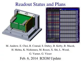
Output Optical Train 1st PZT steering mirror gets a little tight around IMMT SRM 2nd PZT steering mirror BSC OOC IOC Mike Smith
Output Optic Chamber to OMCR beamline from SRM 2nd PZT steering mirror PZT steering mirrors and their controls are duplicates of a pair that we have already installed and commissioned for steering from IMC to main IFO (in-vac); controls are fully implemented in the ASC system (by Rolf). Similar systems can be used for “LIGO I.V”. Piezosystem Jena PSH 5/2 SG-V, PZT tilting mirror mount with strain gauge, and associated drivers and power supplies to OMCT beamline IMCR, IMCT, and SP beamlines to ASRF beamline (roughly 1/3 of AS power) also a convenient path for autocollimator beam, for initial alignment in air from PSL to IMC Mike Smith
OMMT layout Primary radius of curvature, mm 618.4 Secondary radius of curvature, mm 150 Defocus, mm 6.3 Input beam waist, mm 3.03 Output beam waist, mm 0.38 Make mirror(s) by coating a cc lens to get larger selection of ROC Mike Smith
Coupling Loss into OMC Mike Smith
Two in-vac DC PDs two DC PDs OMCT beamsplitter beam dump to OMCT beamline lens
The DC Detection diode • Ben Abbott has designed an aluminum stand to hold a bare photodiode, and verified that the block can radiate 100 mW safely. • A small amplifier circuit will be encased in the stand, and vacuum-sealed with an inert, RGA detectable gas. • Two such assemblies will be mounted together with a 50:50 beamsplitter to provide in-loop and out-of-loop sensors.
Intensity noise • PSL Intensity noise passes straight through to the DC readout. • We have a LIGO-I table-top Intensity Stability Servo (ISS), using in-air ISS DC photodiodes placed on the PSL table after the PMC and Mach-Zehnder, but before the suspended-mass input mode cleaner (IMC) • Do we need to sense intensity noise after the IMC, and/or in-vacuum? • ISS photodiodes could be identical to the DC readout photodiodes. • Only problem: there is little in-vac real-estate available for two ISS PDs. • It appears that the requirements for intensity noise are sufficiently loose that we should be able to obtain the required suppression with the existing in-air sensors. • Should we try to squeeze ISS PDs into the vacuum chambers anyway, for the sake of fidelity?
Required intensity & frequency noise Require RIN < 3e-8 and freq noise < 1e-8 Rob Ward using rsenoise from Jim Mason
The Output Mode Cleaner • Purpose: filter RF sidebands and HOMs of both carrier and RF sidebands; pass carrier and GW sidebands. • Minimize introduction of LF noise: In-vacuum, on a seismic stack. • We can use a 3 or 4-mirror OMC. • 4 mirrors halves the chance of accidental resonance of HOMs • But 3 mirrors rejects “wrong” polarization, which is more likely to contain noise than useful GW information • We could use a PSL PMC, if a spare can be found; or have one as a backup • Either way, should be easy to build new one • Off the shelf mirrors. • An easy spacer (Al or SS) • Mechanically mount the mirrors, 3-point. • The only glue is to mount the mirror on PZT. • Cheap, quick, and easy to re-do. • Input and output couplers would be wedged. • Design Considerations: • Astigmatism, counter propagating modes, accidental HOM resonances, RF sideband suppression. • Measurement of AP beam structure. PSL PMC
OMC HOM filtering 4-mirror cavity 3-mirror cavity Both: T=1%, finesse=300, carrier transmission = 94.6%
OMC, four mirror design Mike Smith • Internal reflection angles must be small to maximize reflectivity of OTS mirrors • Reflection angle on curved mirror should be small to minimize astigmatism • Internal angles should be large to minimize counter-propagating modes (depends on mirror BRDF) • Mirrors mounted mechanically, on 3 points (no glue) • curved mirror: off-the-shelf CVI laser mirror with ROC = 1 m ± 0.5% • Fixed spacer should be rigid, vented, offset from table • Design subject to change!
Transverse mode spacings (Guoy phase) vs ROC These red zones indicate that, for all modes up to n+m=6, Carrier < 0.05 % 33MHz < 1 % 166MHz < 0.1 % (Finesse = 1000, nominal ROC = 1 m) Rob Ward Curved mirror ROC
Finesse and filtering of RF, HOMs • input and output couplers with • 0.3% transmission finesse=950, fpole = 0.34 MHz • 0.5% transmission finesse=590, fpole = 0.55 MHz • 1.0% transmission finesse=300, fpole = 1.08 MHz • 2.0% transmission finesse=150, fpole = 2.15 MHz • Higher finesse means better filtering of RF sidebands and HOMs, but it … • makes the DC readout more sensitive to OMC length noise; • makes it harder to lock (higher BW required on servo); • has higher stored power, easier for contaminants to burn on to the mirrors; • the exact finesse obtained depends more strongly on the losses in the OMC. • The lower finesse should be sufficient for filtering, but we run the risk of accidental HOM resonances due to some imperfection.
Dependence of finesse on losses 300 ppm/mirror
Controlling the OMC • OMC length signal: • Dither-lock? • Should be simple; we’ll try this first. • PDH reflection? • There’s only one sideband, but it will still work. • Servo: • Will proceed with a simple servo, using a signal generator and a lock-in amp. • Feedback filters can easily be analog or digital. • Can use a modified PMC servo board for analog. • Can use spare ADC/DAC channels in our front end IO processor for digital. • Digital is more flexible, easy to implement, and “free” • PZT actuation
Analog servo option Jay Heefner
Further Plans • Quantify: • Expected noise: shot, intensity, frequency, … • OMC length noise • ISS requirements. • Study MZ phase noise effects • PRC/SRC/MICH/DARM loop couplings • How much do fluctuations in the loss mismatch ‘quadrature’ couple into the GW signal? • Sensing the OMC-input beam alignment? • IFO alignment stability? We have an ASC system, but no WFSs. • Finalize design, procure/build PZT mirrors, OMC, OMMT, DCPDs, electronics • Vent, install, align, commission, and begin experiments.