Download
1 / 35
350 likes | 459 Vues
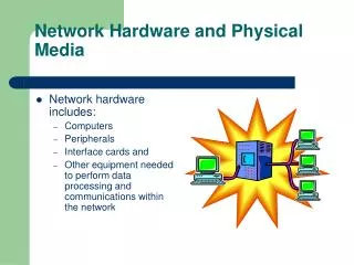
The physical network. Unit objective: Identify network cables and connectors, and use networking tools. Topic A. Topic A: Network cable and connector types Topic B: Cable and connector properties Topic C: Networking tools. Fiber optic cable. Carries light-based data

E N D
The physical network Unit objective: Identify network cables and connectors, and use networking tools
Topic A Topic A: Network cable and connector types Topic B: Cable and connector properties Topic C: Networking tools
Fiber optic cable • Carries light-based data • Strands of glass or plastic • Components contnued
Fiber optic connectors • ST • SC • LC • Other connectors
Twisted-pair cable • Copper wire • Unshielded twisted-pair • Shielded twisted-pair • Connectors • RJ-45 • RJ-11
Coaxial cable • Found in older networks continued
Coaxial cable, continued • RG-8 and RG-58 used in Ethernet • RG = Radio Guide • Stranded or solid • Impedance in ohms, Ω • Thicknet cables are RG-8 • Thin Ethernet cables are RG-58
Topic B Topic A: Network cable and connector types Topic B: Cable and connector properties Topic C: Networking tools
Fiber optic cable • Two types • Single-mode • Multimode • Commonly used for long distances and backbones • Benefits: • Thinner and lighter weight • Higher carrying capacity • Use of digital signals • Less signal degradation • Less interference • Non-flammable • More secure
Stranded vs. solid • Solid • Thicker, more protective covering • Less flexible • Best for longer network runs and fixed wiring • Stranded • Thinner protective covering • More pliable • Useful for shorter-distances and movable wiring
Straight-through and cross-over • Straight-through • TP cable; both ends follow either 568A or 568B • Used to connect computers to hub or switch • Cross-over • TP cable; one end is wired using 568A, and the other using 568B • Used to connect two computers together
T1 crossover cable • Connects two T1 devices together without a network device between them
Topic C Topic A: Network cable and connector types Topic B: Cable and connector properties Topic C: Networking tools
Coax crimper • Terminating a coaxial Thinnet cable to a BNC connector
Using a punchdown tool • Insert the wire between the two metal blades on the punchdown block. There is one wire per contact in the punchdown block. • Place the punchdown tool on top of the wire. (Remember to have the correct side of the tool facing up.) • Apply pressure to the wire until you hear a snap. This snap is from the spring mechanism inside the tool.
Cable testing device • Test physical cables and network functions • Single LAN type device or multiple LAN type device
Physical cable tests • Locating incorrectly wired cables, open cables, and shorts • Locating missing cables • Locating cables that don’t support your network type • Testing hub connections • Testing PC connections • Testing installed cables • Testing patch cables • Locating and tracing inactive cables
Network function tests • Verifying that a PC or switch is powered on • Specifying whether a device is a network PC or a switch • Displaying the maximum network connection speed to the device • Verifying PC-to-switch speed, and data transmission and port speed or duplex mismatch • Verifying switch-to-switch data transmission • Determining if a straight-through or crossover patch cable is required • Finding speed bottlenecks on LANs • Monitoring a LAN link between two devices
Toner probe • Amplifier probe • Locate, identify, and trace wires or cables • Works with a tone generator
Using a tone probe • Set the tone generator to tone. • Test the tone generator. • Connect the tone generator to one end of the cable you want to trace. • Use the probe to identify where the cable comes into your patch panel or 110 block. Move to the cable bundle and identify the cable in the bundle that runs to where you’ve connected the tone generator. • Disconnect the tone generator and turn it off.
Loopback plug • Test ports • Specific to type of port • Ethernet loopback • 10 and 100 Mbps • Gigabit • Network loopback plug - can make your own or buy commercial
Multimeters • Use to measure electricity from power supply or computer component • Available in digital and analog models
Measuring resistance • Turn off the device you’re measuring and disconnect it from its power source • If necessary disconnect the device from its circuit • Set the multimeter to read resistance • Touch the two leads of the multimeter together • Touch the black and red probes to either side of the circuit to be measured, and read the resistance from the meter’s display
Measuring voltage • The power supply must be on • Set your multimeter to read either DC or AC voltage • Touch the black probe to the ground, and touch the red probe to the spot where you want to measure the voltage
Measuring current • Break the circuit • Insert the meter in the break • Read the current flowing through circuit • Can also use an ammeter or clamp-ion ammeter to measure current flow
Measuring continuity • Set multimeter to display resistance • Look for circuits with zero resistance • If your multimeter includes a continuity mode, you can use that. • In continuity mode, multimeter sounds a tone whenever it detects a closed circuit
Unit summary • Identified network cables and connectors, and used networking tools