Download
1 / 70
720 likes | 1.05k Vues
SHALE GAS DRILLING. EVER GET THESE EMAILS…. Here’s my problems with these well intended messages: Often quoted from the News Media Often quoted out of context Supposed “reserves” data given without stating what level of reserves those numbers are

E N D
EVER GET THESE EMAILS… Here’s my problems with these well intended messages: Often quoted from the News Media Often quoted out of context Supposed “reserves” data given without stating what level of reserves those numbers are Claims made without knowledge of what the real energy picture is It takes hours to unravel one of those emails, to cross check data, look up reserves, compare like terms, etc. Sent: Thu, February 10, 2011 11:33:09 AMSubject: Comments?A new drilling technique is opening up vast fields of previously out-of-reach oil in the western United States, helping reverse a two-decade decline in domestic production of crude.Companies are investing billions of dollars to get at oil deposits scattered across North Dakota, Colorado, Texas and California. By 2015, oil executives and analysts say, the new fields could yield as much as 2 million barrels of oil a day -- more than the entire Gulf of Mexico produces now…. > Here's an astonishing read. Important and verifiable information:>> About 6 months ago, the writer was watching a news program on oil and one of the Forbes Bros. was the guest. The host said to Forbes, "I am going to ask you a direct question and I would like a direct answer; how much oil does the U.S. have in the ground?" Forbes did not miss a beat, he said, "more than all the Middle East put together.">> The U. S. Geological Service issued a report in April 2008 that only scientists and oil men knew was coming, but man was it big…
Energy Overview Reserves Analysis Well Design & Drilling Fracking Problems
Estimated US Energy Use – 2009 Energy Wasted 58% Nuclear 9%c Other 5% Hydro 3% Residential 12% Natural Gas 25% Commercial 9% Energy Sources Energy Uses Industrial 23% Coal 21% Transport 29% Oil 37%
Estimated US Energy Use – 2009 Energy Wasted 58% 85% of Waste from 2 Sources Transportation (autos) 37.0 Electricity Generation 47.6%
42% 53%
LARGEST GAS RESERVES Current US Shale Gas Estimated Reserves are 750 TCF BUT comparing to this chart might be comparing APPLES and ORANGES Since Shale Gas Extraction is so new, this chart may not include ANY of the world’s shale gas * Recoverable
US SHALE GAS RESERVES Source: US Energy Information Adminstration BUT! USGS came back and revised the EIA’s data for the Marcellus down by 79.5% to 84 TCF Total This is a whopping 55% of the total Might Acutally be 153.6 TCF??
When the distance between the top of the target shale and the bottom of the aquifer is small, ONLY experienced operators should be drilling!
Production Decline Curve • Production rates are a function of reservoir pressure. • As production is removed from the reservoir, pressure decreases and therefore production decreases. • At some point, the economic limit is reached and decisions about the reservoir/ well must be made. Economic Uneconomic
Production Enhancement Hydraulic Fracturing • Fracture reservoir rock (up to 500’ from perforations) with high pressure fluid & place a permeable proppant material into the fracture channel • Fracture remain open after pressure is reduced providing a high conductivity pathway for reservoir fluids to flow to the well
Production Enhancement Hydraulic Fracturing • In North America, 58 percent of new gas wells and 38 percent of new oil wells are hydraulically fractured. • Hydraulic fracturing is also being used more often in high permeability formations 58 % New Gas Wells 38 % New Oil Wells
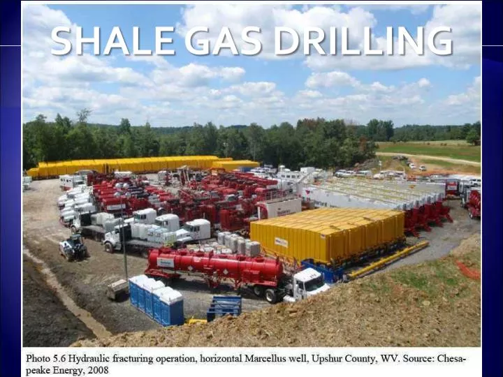
Production Enhancement Hydraulic Fracturing A Frac Job takes considerable equipment
Environmental Overview
Claims Against Fracking • Cows killed • Drinking water burns • Skin rashes • Contaminated soils • Air pollution • Dust
Overview of One Experts Opinion • Conversation with Dr. Ian Duncan • Associate Director, Texas Dept of Economic Geology • Areas of Dimock, PA have historical records of NATURAL methane seepage into underground aquifers • He notes that the local Ag Extension service used and still do provide a warning brochure, which he has a copy of, advising prospective new residents of the area of the dangers of methane in their drinking water as home have blown up in the past as a result. This was a problem in the 1950’s and 60’s. • Evidence shows that more often than not, it is the natural seepage of methane that is causing problems with their drinking water, not Fracking as reported by the News Media and YouTube
Separating FACT from FICTION • Conversation with Dr. Ian Duncan • Associate Director, Texas Dept of Economic Geology • Over 1000 supposed claims of environmental disasters associated with Fracking • Only 30-40 have been filed with the Environmental Defense League • 6 identified as possible issues • 3 found incorrectly attributed frackingwith naturally occuring methane seepage into underground aquifers • 3 found with bad cement jobs (Wyoming, Colorado, Ohio) • 2 of those had prior knowledge of the cement situation but Fracked anyway – Therefore only 1 instance of fracking causing unintentional problems • Dr. Duncan notes that a paper will be published this year with his results
Separating FACT from FICTION MASSACHUTTES INSTITUTE OF TECHNOLOGY – July 2011 (http://web.mit.edu/mitei/research/studies/documents/natural-gas-2011/NaturalGas_Chapter%201_Context.pdf) “There has been concern that these fractures can also penetrate shallow freshwater zones and contaminate them with fracturing fluid, but there is no evidence that this is occurring. There is, however, evidence of natural gas migration into freshwater zones in some areas, most likely as a result of substandard well completion practices by a few operators.”
Separating FACT from FICTION Environmental Protection Agency Study started in 2010 Results due in 2012
EPA STUDY IN PROGRESS EPA RSTUDY TO BE COMPLETED BY 2012
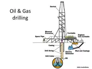
Well Design during drilling Blowout Preventer – Monitor & Controls the pressure within each casing string of the well Casing String – Successive sections of pipe of decreasing diameter set one inside the other and cemented in place Blowout Preventer Surface `` Casing Strings
How is Casing Installed? • Drill 36” hole to design depth • Slide 30” casing to depth within 36” hole • Cement 30” casing to 36” hole • Drill 24” hole thru cement in 30” casing to design depth • Slide 20” casing to depth within the 24” hole • And so on …. Surface 30” Casing 36”hole 24”hole 20” Casing
Typical Well Casing Program • 30” Casing = Conductor Pipe (hung at surface; it is drilled or driven) • 20” Casing = Surface Casing (hung at surface; may not be necessary, depends on geology) • 13 3/8” Casing = Intermediate Casing (hung at the surface) • 9 5/8” Casing = Intermediate casing (depending on design, could be hung off of 13 3/8”) • 7” Liner = Not a casing per se because it is hung off the end of the 9 5/8” casing; it doesn’t run to the surface Casing Size Depth 500 ft 30 in (36”hole) 3,000 ft 20 in (26”hole) 13 3/8 in (17 ½” hole) 7,000 ft 9 5/8 in (12 ½” hole) 10,000 ft 7 in Liner (8½” hole) 15,000 ft
Well Casing Program • Why is casing needed? • Protect freshwater aquifers that might be present in the subsoil • Prevents contamination between rock strata layers • Contain any unusual pressure in the layers of rock strata that might be encountered • Prevent borehole collapse while drilling deeper • Provide control of drilling mud being pumped down-hole Freshwater Aquifer Low Pressure Zone or future producing zone Wellbore thru the rock strata High Pressure Zone Black Gold! Cap Rock
Well Design during completion Xmas Tree– Monitor & Controls the pressure within the each casing of the well while allowing the well to flow to the surface Perforations – Holes shot thru the casing to allow fluid to flow into the wellbore Down-hole Completion Equipment – Devices & tools installed in the well to control which reservoir is produced and to give real-time data Xmas Tree Surface `` Down-hole Completion Equipment` Perforations
Well Design during completion To Production Facilities Xmas Tree Production Tubing – A string of pipe that runs from the producing zone to the wellhead in which oil and/or gas flows to the surface facilities Surface `` Down-hole Completion Equipment` Perforations
Types of Well Design • “Straight-hole” • Directional or “Deviated Well” • “Horizontal Well” Black Gold! Cap Rock
Deviated Well • Why drill a deviated well? • Known fault can cause an unplanned deviation from the projected drill path • High pressure zones might exist to one side of a fault • Subsurface “debris” like ancient reefs could cause a slower drill rate (ROP) than desired (time is money!) High Pressure zones behind fault Fault Black Gold! Cap Rock
Deviated, Horizontal Wells • Why drill a horizontal well? • Low permeability reservoirs are best produced by horizontal wells, the ultimate in “deviated well” • Three kinds of horizontal wells, long/short/medium radius: • Long = 10 per 100ft • Medium = 20 per 100ft • Short = 40 per 100ft Target Reservoir
Horizontal Well Procedure • At start of deviation, replace drillbit with a “bent sub”, gyroscope, steerable mud motor & bit • Add logging-while-drilling (LWD) unit & power pack within 20 ft of bit • Slowly rotate drillstring to prevent “sticking” & start “pushing” steerable system forward while flowing mud to mud motor • Drill while being pushed forward & steer system as need be to maintain horizontal direction
Multilateral, Horizontal Wells • Added advantage of horizontal well design is to include “Multilaterals” (additional boreholes from the same drillsite) • From one wellsite, several sections of the reservoir can be accessed & produced Significant Production Increase Drillsite Plan view