Download
1 / 27
300 likes | 542 Vues
The Integrated Science Instrument Module Ground Test. Matt Greenhouse ISIM Project Scientist NASA Goddard Space Flight Center 23 July 2010. ISIM is the science instrument payload of the JWST. ISIM is one of three elements that together make up the JWST space vehicle

E N D
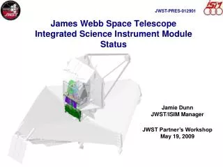
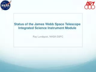
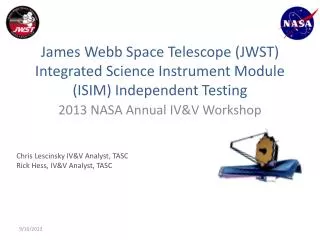
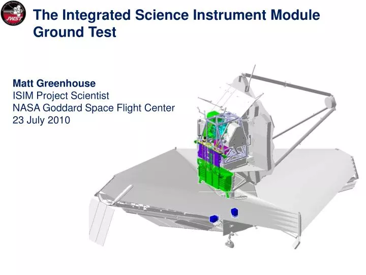
The Integrated Science Instrument Module Ground Test Matt Greenhouse ISIM Project Scientist NASA Goddard Space Flight Center 23 July 2010
ISIM is the science instrument payload of the JWST • ISIM is one of three elements that together make up the JWST space vehicle • Approximately 1.4 metric tons, ~20% of JWST by mass or cost • The ISIM system consists of: • Four science instruments • Nine instrument support systems: • Optical metering structure system • Electrical Harness System • Harness Radiator System • ISIM electronics compartment (IEC) • ISIM Remote Services Unit (IRSU) • Cryogenic Thermal Control System • ISIM Command and Data Handling System (ICDH) • Flight Software System • Operations Scripts System Presentation to STScI Calibration Workshop: Approved for public release; distribution unlimited.
The ISIM system completed CDR during March 2009 • All science instrument ETU test programs have been completed • All instrument ETUs have been delivered • Flight model integration is underway on all instruments and supporting systems NIRCam Engineering Test Unit NIRSpec Development Model MIRI Verification Model FGS Engineering Model Presentation to STScI Calibration Workshop: Approved for public release; distribution unlimited.
Making sure it all works …. • Science instruments and each of their 9 supporting systems are individually flight qualified prior to delivery to ISIM I&T • Ground testing at the ISIM element level is designed to (no order): • Verify instrument alignment with the ISIM structure • Verify instrument compatibility with the: harness system, ICDH, IRSU, FSW, & OSS • Verify design performance wrt EMI/EMC • Verify instrument compatibility with the FGS • Verify SI-to-SI compatibility for parallel mode dark calibration • Characterize thermal performance for model validation • Characterize ISIM performance stability for model validation • Correlate instrument performance in ISIM to instrument-level test results • Verify workmanship for flight environment • Measure mass properties • Approximately 200 requirements to be verified at ISIM assembly level • ISIM is subsequently delivered to observatory-level I&T as a flight qualified element Presentation to STScI Calibration Workshop: Approved for public release; distribution unlimited.
I&T Responsibility Execution NASA NGST OTE/ISIM I&T ITT GSFC SSDIF, JSC 32 ESA / Arianespace Cryo Optics Test Pathfinder Optics Integration Pathfinder Cryo Optics Test OTE Pathfinder Structure NG M8 GSFC SSDIF JSC 32 Launch Observatory EM Test Bed (EMTB) NG R8 Facility Sunshield Pathfinders (EPF/IVA) NG M8 N/A ISIM is one of three element-level test programs ISIM I&T GSFC SSDIF OTE I&T OTE Structure I&T NG M8 GSFC SSDIF Propulsion Module I&T NG M3 Spacecraft Panel I&T NG M8 Complete Observatory I&T Launch Site I&T LV Integ CSG S5C, S5B, BAF, ZL3 NG M8, LATF, M4 Vibe Spacecraft Element I&T NG M8, M4 TV Sunshield I&T NG M8 Presentation to STScI Calibration Workshop: Approved for public release; distribution unlimited.
ISIM Test Verification Flow INS-20xxx TST-20900 TST-21000 Receive Flight ISIM Electronics Compartment Structure with Backbone Harness FLT IEC Integration (FLT E-box) IEC Sine & Random Vibe Test IEC Mass Properties dI TST-20700 TST-20600 TST-20910 System Functional Test Alignment Metrology Deintegrate For Vib and Mass Props TST-21000 ISIM Gravity Release Test ISIM Mass Properties INS-20xxx rI Receive Flight ISIM Structure Integrate: HAS,CHA, HR, Harness, SIs TST-20400 TST-20800 TST-20900 TST-21100 dI rI Cryo Thermal Vacuum Test w/TMS and OSIM EMI/EMC Test Acoustics Test (ISIM & IEC) Sine Vibe Test (ISIM Only) TST-21300 INS-21301 TST-30000 TST-21200 OTE Integration & Test Program Cryo Thermal Vacuum Test w/TMS and OSIM OTE Cryo Vac At JSC Clean, Inspect, Pack & Ship rI – Re-Integrate ISIM and IEC dI – De-Integrate ISIM and IEC
ISIM will be tested at ~35 K in the GSFC SES chamber using a cryogenic telescope simulator (OSIM) SES chamber (27 x 40 ft) LN2 Shroud LHe shroud ISIM OSIM Vibration Isolation Supports LHe shroud installation and test completed July 09 Fold Mirror 3 Tip/Tilt Gimbal Assembly OSIM Primary Mirror Alignment Diagnostic Module Presentation to STScI Calibration Workshop: Approved for public release; distribution unlimited.
Major ground support equipment required for ISIM I&T • Primary ground support equipment: • Cryogenic Optical Telescope Simulator (OSIM) • Simulates Optical Telescope Element (OTE) with high fidelity • OSIM Beam Analyzer • Space environment simulator LHe shroud • Enables ISIM testing at operating temperature • Cryogenic photogrammetry system • Enables metrology of ISIM structure at operating temperature • ISIM Test Platform (ITP) • Simulates OTE mechanical interface at cryogenic operating temperature • ISIM simulators provided to support SI-Level testing: • Ambient science instrument mechanical interface fixture (ASMIF) • Simulates ISIM structure mechanical interface for each instrument with high fidelity • Science instrument test sets (SITS) • Simulates ICDH for each instrument Presentation to STScI Calibration Workshop: Approved for public release; distribution unlimited.
The ISIM structure has passed key verification tests for cryogenic dimensional reputability and distortion • Carbon-fiber/cyanate-ester composite material • Primary launch-load bearing structure (warm launch) • High precision optical requirements • Key dimensional requirements for thermal cycling (300 to 30 K) verified to > 25 micron precision • Repeatability: 80 microns • Distortion: 500 microns • Key tests to-go: • Cryogenic and ambient strength proof tests • Modal survey Presentation to STScI Calibration Workshop: Approved for public release; distribution unlimited.
Key Thermal Performance Test Objectives • Best-controlled opportunity for ISIM thermal testing • 460 mW total power allocation to cryogenic portion of ISIM • Very sensitive to workmanship • Thermal test objectives: • Thermal model correlation and validation • Workmanship/performance of critical thermal elements (heat straps, harnesses, MLI, contamination control heaters/algorithms, trim heaters, temp sensors • SI stability during multi-instrument operation • Sensitivity of ISIM to backplane interface temperature • MIRI thermal performance, heat load measurement within heat shield • IEC thermal balance, thermal cycling, transient stability, steady state surface and electronics box temperatures Presentation to STScI Calibration Workshop: Approved for public release; distribution unlimited.
ISIM enclosure and passive cryogenic radiators replaced by precision controlled cryo-pannels • Flight radiators integrated at OTIS assembly level • Q meters used to verify thermal loads and flight heat strap performance • MIRI cooling provided by GSE cryo-cooler compressor Flight high purity aluminum heat strap assemblies Presentation to STScI Calibration Workshop: Approved for public release; distribution unlimited.
IEC and Harness Radiator Flight Configuration Presentation to STScI Calibration Workshop: Approved for public release; distribution unlimited.
The ISIM electronics compartment successfully addresses one of most difficult engineering challenges of the JWST • The IEC accommodates 11 warm electronics boxes that must reside on the cryogenic side of the sunshield close to the science instruments • Rejects ~220 W of power to space in a controlled beam pattern to achieve required observatory thermal balance and avoid thermal stray light • Radiator beam pattern verified in prototype test • Key test to-go: full thermal balance Flight Shell Flight Baffle Presentation to STScI Calibration Workshop: Approved for public release; distribution unlimited.
IEC & HR test shrouds simulate flight cryogenic environment with high fidelity IEC ~ 25 K Test Shroud HR (~ 20 - 25 K) Shroud lined with black honeycomb HR with flight harnesses Presentation to STScI Calibration Workshop: Approved for public release; distribution unlimited.
Flight cryogenic radiators are replaced by a surrogate thermal management system LN2 Shroud GHe Shroud IEC Two Shroud Assembly LN2 shroud surrounded by dedicated He shroud plumbed to the primary chamber He shroud. Harness Radiator with –V1 Shroud • Surrogate Thermal Management System (STMS) • Comprised of actively controlled panels to produce environment of flight TMS to ISIM (Region 1) Vibration Isolation System Optical Telescope Element Simulator (OSIM) Presentation to STScI Calibration Workshop: Approved for public release; distribution unlimited.
Approximately 150 optical requirements are verified or cross checked during ISIM element testing • Only opportunity for testing integrated instrument suite with flight-like beam of flight-like image quality/wavefront • Comprehensive optical performance test plan confirms alignment, image quality, wavefront sensing capability • OPRG1 • Basic optical capabilities • OPRG2 • Wavefront and focus requirements • Calibration requirements for the MIMF wavefront sensing algorithm • OPRG3 • Pupil shear and rotation requirements • OPRG4 • Fields of view, vignetting, stray light • Absolute pointing of ISIM • OPRG5 • Co-boresight stability vstemperture • OPRG6 • Performance of NIRCam wavefront sensing and control components Presentation to STScI Calibration Workshop: Approved for public release; distribution unlimited.
Science Instrument (SI) sensitivity verification • SI-level requirements cover every filter and mode of the instrument • Verified at instrument level as part of their qualification ahead of delivery to ISIM I&T • Component-level testing combined with models • Sensitivity models held under configuration control • Spec values used for OTE parameters • Sensitivity benchmarks will be measured on SI internal sources during ISIM-element testing for correlation with SI-level test results • POM contamination monitored with witness plates and NIRSpec spectroscopy on OSIM continuum sources Presentation to STScI Calibration Workshop: Approved for public release; distribution unlimited.
Each of two cryogenic test cycles require ~20 weekswith ~ 6 weeks used for cool-down and warm-up Presentation to STScI Calibration Workshop: Approved for public release; distribution unlimited.
Learn more at: www.jwst.nasa.gov Watch the ISIM being built at: www.jwst.nasa.gov/webcam.html Read about JWST science mission objectives at: http://www.jwst.nasa.gov/science.html Collaborate on JWST science investigations: http://www.stsci.edu/institute/conference/jwst2011 Presentation to STScI Calibration Workshop: Approved for public release; distribution unlimited.
Presentation to STScI Calibration Workshop: Approved for public release; distribution unlimited.
ISIM Instrument characteristics wallet card Presentation to STScI Calibration Workshop: Approved for public release; distribution unlimited.
NIRCam will provide the deepest near-infrared images ever and will identify primeval galaxy targets for the NIRSpec • Developed by the University of Arizona with Lockheed Martin ATC • Operating wavelength: 0.6 – 5.0 microns • Spectral resolution: 4, 10, 100 • Field of view: 2.2 x 4.4 arc minutes • Angular resolution (1 pixel): 32 mas < 2.3 microns, 65 mas > 2.4 microns • Detector type: HgCdTe, 2048 x 2048 pixel format, 10 detectors, 40 K passive cooling • Refractive optics, Beryllium structure • Supports OTE wavefront sensing Presentation to STScI Calibration Workshop: Approved for public release; distribution unlimited.
Fixed Slits and IFU Aperture 3.4’ Detector Array 3.6’ The NIRSpec will aquire spectra of up to 100 galaxies in a single exposure • Developed by the European Space Technology Center (ESTEC) with Astrium GmbH and Goddard Space Flight Ctr • Operating wavelength: 0.6 – 5.0 microns • Spectral resolution: 100, 1000, 3000 • Field of view: 3.4 x 3.4 arc minutes • Aperture control: programmable micro-shutters, 250,000 pixels • Angular resolution: shutter open area 203 x 463 mas, pitch 267 x 528 mas • Detector type: HgCdTe, 2048 x 2048 pixel format, 2 detectors, 37 K passive cooling • Reflective optics, SiC structure and optics Presentation to STScI Calibration Workshop: Approved for public release; distribution unlimited.
Aperture control: 250, 000 programmable micro-shuttersSystem at TRL-8 and delivered to ESA June 2010 203 x 463 mas shutter pixel clear aperture, 267 x 528 mas pitch, 4 x 171 x 365 array Human Hair 90 um Dia. Presentation to STScI Calibration Workshop: Approved for public release; distribution unlimited.
The MIRI instrument will detect key discriminators that distinguish the earliest state of galaxy evolution from more evolved objects • Developed by a European Consortiumand JPL • Operating wavelength: 5 - 29 microns • Spectral resolution: 5, 100, 2000 • Field of view: 1.9 x 1.4 arc minutes broad-band imagery • R100 spectroscopy 5 x 0.2 arc sec slit • R2000 spectroscopy 3.5 x 3.5 and 7 x 7 arc sec integral field units • Detector type: Si:As, 1024 x 1024 pixel format, 3 detectors, 7 K cryo-cooler • Reflective optics, Aluminum structure and optics Optical Assembly Structural/Thermal Model Presentation to STScI Calibration Workshop: Approved for public release; distribution unlimited.
The FGS provides imagery for telescope pointing control & imaging spectroscopy to reveal primeval galaxies and extra-solar planets • Developed by the Canadian Space Agency with ComDev • Operating wavelength: 0.8 – 4.8 microns • Spectral resolution: Broad-band guider and R=100 science imagery • Field of view: 2.3 x 2.3 arc minutes • R=100 imagery with Fabry-Perot tunable filter and coronagraph • Angular resolution (1 pixel): 68 mas • Detector type: HgCdTe, 2048 x 2048 pixel format, 3 detectors • Reflective optics, Aluminum structure and optics Presentation to STScI Calibration Workshop: Approved for public release; distribution unlimited.