Download
1 / 90
900 likes | 907 Vues
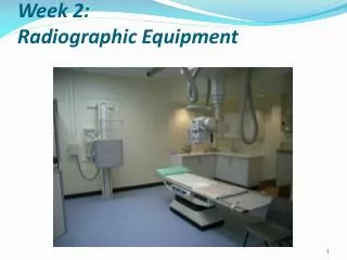
RAD TECH A WEEK 2 RADIOGRAPHIC EQUIPMENT Spring 2009. Radiographic Room. OBJECTIVES. IDENTIFY GENERIC COMPONENTS OF THE RADIOGRAPHIC EQUIPTMENT DESCRIBE VARIOUS PLANES OF X-RAY TUBE AND TABLE MOVEMENT DISCUSS CONTRAST & DENSITY “ EXPOSURE FACTORS”. X-RAY TUBE.

E N D
RAD TECH A WEEK 2 RADIOGRAPHIC EQUIPMENT Spring 2009
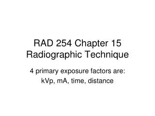
OBJECTIVES • IDENTIFY GENERIC COMPONENTS OF THE RADIOGRAPHIC EQUIPTMENT • DESCRIBE VARIOUS PLANES OF X-RAY TUBE AND TABLE MOVEMENT • DISCUSS CONTRAST & DENSITY “ EXPOSURE FACTORS”
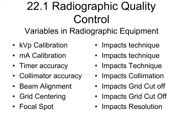
X-RAY TUBE • MADE OF PYREX GLASS TO WITHSTAND HIGH HEAT LOAD • IS GAS EVACUATED • (so electrons won’t collide with the air molecules in the tube)
XRAY TUBE HOUSING • MADE OF LEAD AND STEEL • TO ABOSRB ANY STRAY RADIATION • TO PREVENT X-RAY PHOTONS TO LEAK FROM THE TUBE
THE X-RAY TUBE • Glass encased in a sturdy lead and steel housing • Primary components ANODE (+) & CATHODE (-)
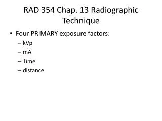
X-Ray Machine • Purpose: • provide a specific current (mA) & voltage (kV) to the x-ray tube • convert electrical energy to electromagnetic energy (x rays) in a controlled manner • control the energy of the x-ray photons • control the number of photons
THE X-RAYTUBE • The X-Ray tube is the single most important component of the radiographic system. It is the part that produces the X-rays
X-rays are produced when electrons strike a metal target. The electrons are released from the heated filament and accelerated by a high voltage towards the metal target. The X-rays are produced when the electrons collide with the atoms (electrons) of the metal target. How Are X-rays Made?
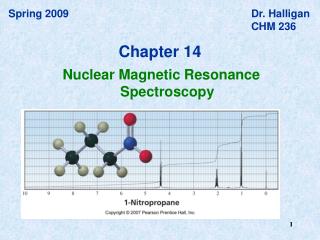
X-ray PHOTONS • Electromagnetic waves • Shorter wavelength and higher energy than normal light. • Wave-particle duality • Photons can be described both as waves and particles.
The Electromagnetic Spectrum • X-rays have wavelengths much shorter than visible light, but longer than high energy gamma rays MEASURED IN ANGSTROM 0.1 – 0.5 FOR X-RAYS
PRODUCTION OF X RAYS Requirements: • a source of fast moving electrons • must be a sudden stop of the electrons’ motion • in stopping the electron motion, kinetic energy (KE) is converted to EMS energies • Infrared (heat), light & x-ray energies
How “X-rays” are created • Power is sent to x-ray tube via cables • mA (milliamperage) is sent to filament on cathode side. • Filament heats up – electrons “boil off • Thermionic emission • Negative charge
How “X-rays” are created • Positive voltage (kVp) is applied to ANODE • Negative electrons = attracted across the tube to the positive ANODE. • Electrons “slam into” anode – suddenly stopped. • X-RAY PHOTONS ARE CREATED
How “X-rays” are created • Electron beam is focused from the cathode to the anode target by the focusing cup • Electrons interact with the electrons on the tungsten atoms of target material • PHOTONS sent through the window PORT – towards the patient
How “X-rays” are createdSEE: MAN MADE RADIATION (PG.93) TO PRODUCE X-RAYS YOU NEED: • A SOURCE OF ELECTRONS • A FORCE TO MOVE THEM QUICKLY • SOMETHING TO STOP THEM SUDDENLY
e- e- e- e- e- e- e- e- e- e- e- e- e- e- e- e- e- e- e- e- e- e- e- e- e- e- e- e- e- e- e- e- e- e- e- e- e- e- e- e- X-ray Production target electrons anode • Electrons move at high speed (KE) • Collide with target on anode • KE of electrons converted to x rays & heat
HIGH VOLTAGE TO ANODE – ATTRACTS – ELECTRONS FROM CATHODE CURRENT TO STATOR CAUSES ROTATION OF ANODE
Molybdenum or Graphite base Anodes - Target • Rotating Anodes • 2” to 5” disk (focal track) Cu W • Common target material is Tungsten
X-ray Tube Anode • Tungsten anode disk • Stator and rotor make up the induction motor • Rotation speeds • Low: 3,000 – 3,600 rpm • High: 9,000 – 10,000 rpm • Molybdenum stem (poor heat conductor) connects rotor with anode to reduce heat transfer to rotor bearings • Focal track area (spreads heat out over larger area than stationary anode configuration)
The ‘BUCKY’ • The bucky is the device in the table or chest board that holds the film cassette. The ‘bucky’ is like a drawer that opens and closes to insert and remove the film cassette.
Tables • Tilting rooms are designed for both diagnostic and fluoroscopic work • Tilting models usually tilt to 90 degrees in one direction and 15 – 30 degrees in the other direction • Tilting models include ancillary equipment; footboard, shoulder support, handgrips, compression bands
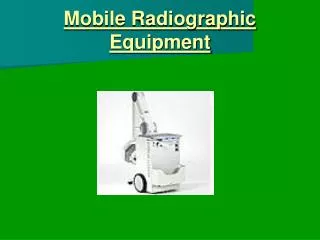
Tube Supports • Designed to help technologists with various tube locations for creative imaging. • Tube suspension systems are available in 5 versions
Tube Movement • Longitudinal • Transverse • Vertical • Angling or Rolling • Rotating • Telescoping
COLLIMATOR • ATTACHES DIRECTLY BELOW THE X-RAY TUBE • SERVES AS A X-RAY BEAM LIMITING DEVISE • CONTROLS THE SIZE AND SHAPE OF X-RAY FIELD