Download
1 / 6
60 likes | 338 Vues
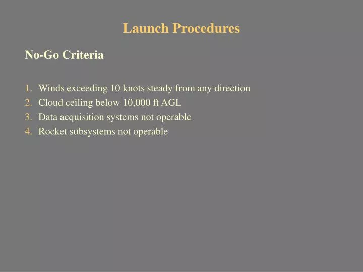
Launch Procedures. No-Go Criteria Winds exceeding 10 knots steady from any direction Cloud ceiling below 10,000 ft AGL Data acquisition systems not operable Rocket subsystems not operable. Launch Procedures (page 2). Pre-Test Preparation Launch rail installed on launch pad.

E N D
Launch Procedures No-Go Criteria • Winds exceeding 10 knots steady from any direction • Cloud ceiling below 10,000 ft AGL • Data acquisition systems not operable • Rocket subsystems not operable
Launch Procedures (page 2) Pre-Test Preparation • Launch rail installed on launch pad. • Rocket motor inspection/clearance from Dugway Proving Ground personnel • Transportation of the rocket motor, subassemblies, launch support equipment (including power supply) to launch site. • Assembly of rocket subsystems at the blockhouse. • Pre-launch checks of all electrical and mechanical components. • Installation of Unity IV Phase II rocket onto launch rail. • Photo/video camera set-up and field of view verification. • Final pre-launch checks of electrical and mechanical systems. • Evacuation of non-essential personnel outside of safety footprint. • Fill oxidizer tank. • Begin launch operations/countdown from the blockhouse.
Launch Procedures (page 3) Test Events • T-minus countdown and launch (see Timeline and Procedures). • Rocket ascends to approximately 10,000 ft AGL. • Deployment of recovery system 150 ft below apogee. • Rocket impact downrange. Post Test Events • Rocket recovery. • Removal of all launch support equipment from launch area. • Review of flight test data and photo coverage.
Timeline and Procedures Time Event ___________________________________ t-7:00 -Arrive at Utah Test and Training Range. -Proceed to the assembly building via Air Force vehicles. t-2:30 -Assembly Team performs maintenance and assembles Unity IV Phase II rocket. -Test and check all mechanical and electrical components. -Enter atmospheric data into the flight controller. t-1:30 -Transport rocket from assembly building to launch pad. -Slide rocket onto the launch rail until stops are met. -Raise launch rail to 90 degrees off of horizontal and secure launch rail angle and support arms. -Assembly Team attaches fins. -All electrical connections are made to the ball valve and it is tested and placed in correct closed position. Disconnect electrical connections to all valves. Solenoid valves are manually checked to be in their correct position. t-1:00 -All personnel at the launch pad enter the block house.
Timeline and Procedures (page 2) Time Event ___________________________________ t-0:30 -Valves are rechecked for their proper open/closed positions by eye. The fill line is connected to the self-sealing connect on the upper solenoid valve. Vent line connected to vent self-sealing connect. -Remove all personnel who are not going to remain in the block house from the footprint area. -Remotely fill the rocket oxidizer tank (25ft). Monitor pressure and fill level through vent line. -Attach the fill line to the first solenoid valve connect and keep the the vent line closed. -Fill until vent line sight glass shows liquid N2O. -Pressurize Tank to 1200 psig with N2. -Record the final pressure. t-0:05 -One person will then go to the rocket and disconnect the oxidizer fill and vent lines from the solenoid valve and vent connects. -Reconnect all electrical connectors to valves. -Seal up access panel.
Timeline and Procedures (page 3) Time Event ___________________________________ t-0:05 Wait for clearance from Range Control t-0:02 Send out warning for countdown. t-30 sec Verify video equipment is running. t-10 sec Activate the power supply and flip to on position. t-0 sec Flip the ignition switch to the on position. The flight controller initiates data recording. The flight controller lights the igniters for six seconds. The flight controller opens the oxidizer valves. Verify launch with video monitor. Altitude Event______________________________ 150 feet below apogee The flight controller sends the signal to separate the nose cone. Nose cone chute deploys. Booster section drogue chute deploys. 5000 AGL Booster section main chute deploys. 0 AGL Rocket impacts at 23 fps. Recover the rocket.