Download
1 / 34
340 likes | 476 Vues
Technion-Israel Institute of Technology Electrical Engineering Department. Programmable Delay of Radar Pulse. Final Presentation of Part A Project number: d1022 November 2003. Students: Guy Apelbaum Yoel Taran Supervisors: Miki Izkovitz Yosi Hipsh. Project Goal.

E N D
Technion-Israel Institute of Technology Electrical Engineering Department Programmable Delay of Radar Pulse
Final Presentation of Part AProject number: d1022November 2003 Students: Guy Apelbaum Yoel Taran Supervisors: Miki Izkovitz Yosi Hipsh
ProjectGoal Delayed Pulse to RF switch Pulse Implementation of an accurate delay system(DS) System receives a pulse as input and transmits it delayed with a given value to RF switch DelaySystem In Out Delay Value
Specifications • Pulse’s appearance frequency lower then 1.5 MHz • Delay value : at range of 1 to 256 nsec • Delay resolution : 0.5 nsec • Pulse width greater then 30 nsec • System operates with pulses at TTL level
General Guidelines • DS implemented as layout • Connected to a PC to communicate with a user • The connection is available through a control system
Control System Main Functionality : Connection between user and DS Features : Transferring value of delay from PC to DS Performing different delay modes User’s PC Control System Delay System
Project Flow Start Definition of Problem Solution Proposal Implementation Of Chosen Solution Hardware Implementation Software Implementation
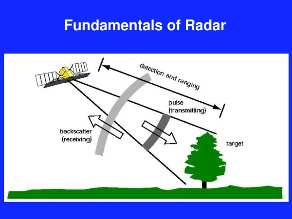
Background The DS implemented here will be a part of ECM system Radar(we trick) works as follows : Time*Velocity = Position where Time = (time of propagation to the target) Velocity = speed of wave Position = distance from radar to the target
DS : delays the signal and shifts the Time calculated by radaradditionally, it increases the energy of the delayed pulsethus, constantly delaying pulses we make radar follow the wrong destination !
Possible Solutions for DS Use of high-frequencyclock (~1 GHz) • The clock starts counting while receiving pulse at input • When reaching the desired delay value pulse is created and is sent to RF switch Pulse IN Pulse OUT Clk(~1GHz) Counter Pulse Generator
Advantages: No pre-calibration of the DS is required Clocks satisfying the desired resolution are available Disadvantages: The demand for 0.5 nsec resolution requires creating pulses with short t_rise Implementation of successful pulse generator is problematic and requires use of high speed digital technology Radar pulse’s shape is unknown – what shape to generate?
Use of delay lines Two delay lines connected in cascade First line : delay range from 1 to 256 nsec resolution of 1 nsec Second line : delay range from 1 to 64 nsec resolution of 0.25 nsec Result : 1 to 256 nsec range is achieved Resolution of the total delay is 0.25 nsec First Line X +/- Dev Second Line X + Y Desired Delay X+Y X Y -/+ Dev
Advantages: No need in creating pulse , the original one is just delayed Original pulse’s shape is maintained Delay lines answering given specifications are available&cheap Disadvantages: The DS need to be calibrated before operating Calibration data need to be stored = additional memory
Delay Lines! The chosen one ? And that’s because of : Simplicity of algorithm used to achieve desired resolution Avoidance of dealing with high speed technology Relatively cheap prices for DS future components
Implementation of the chosen solution: Hardware implementation circuit connecting between PC , controller and DS at first – implementation as wire-up circuit then – implementation as printed layout circuit Software implementation programming the controller which will watch after proper functioning of the system
Schematic view of the wire-up to be built For test proposals – manual controller implemented by dip switches was added In Delay System Out Delay Data PC Controller OR gate DIP switches
Functionality’s Description Delay Lines 3D7408-1 and 3D7408-0.25 lines manufactured by Data Delay Devices Function : delaying pulse at given value 3D7408-1 3D7408-0.25 8 bit input data is all needed for delay lines to function properly The rest of pins are under stable logic value
Controller – implemented by PIC 18f252 manufactured by Microchip Functions : communication with user’s PC communication with delay lines write/read operations with external memory storage of several delay modes applied to DS PIC 18f252 28 I/O pins 2 Mb Program Memory USART,I^2C modules
PIC as a controller of the system - Detailed View ICD 2 Plus demonstration board PC’s GUI EEPROM PIC 18f252 RS-232 USART I^2C Oscilator Power 3D7408-1 3D7408-0.25
PC – any personal computer with RS232 serial port available Functions : read/write operations to/from controller presentation of essential information on the screen
Hardware Characteristics Voltage and Power All units operate of 5 V DC Current driven by the circuit – 350 mA Implementation: Power Source of 9 V AC driving 400 mA entering 5 V DC voltage regulator Speed Rates 1.5 MHz – delay lines max speed 4 MHz – PIC clock frequency
Memory 2 Mb program memory on PIC 256 bytes x 5 RAM on PIC 256 Kbytes x 8 EEPROM on demo board Interfaces GUI : PC – user interface. Implemented by Terminal v1.9b UART : PC – PIC interface. Implemented by USART module located on PIC . Communication via RS232 port
Program Flow Idle initialization Prompts: 1-Calibration 2-Delay 1 Storage of Delay Values 2 Delay Modes
Calibration Prompts: 1-Manually 2-Automatic Storage of Delay Values 1 User enters value It is stored in RAM 2 Data file sent It is stored in RAM
Notes for Calibration: The process is done offline Precedes delay operations The data is stored in RAM (at this point) The data will be stored in EEPROM(soon)
Delay Prompts: 1-Constant Delay 2-Changing Delay(Ch.D) 3-Manually Ch.D Delay Modes 1 Pulse Delayed By a Constant Value 2 Pulse Delay Is Changed With a Given Step 3 Value of Delay Is Manually Entered
Notes for Delay operations: After user transfers delay value it is assigned to delay lines pins by PIC “Enter” pushed during any mode = back to main menu
Software Specifications Development tool to program PIC – ICD 2 Plus demo board compiler – MPLAB C18 emulator – MPLAB ICE 2000 debugger – MPLAB ICD 2 programmer – PICSTART +
Testing Delay line tested by Tektronix 500 MHz Digital Scope good performance – in limitation of measuring equipment Pulse Generator Digital Scope 3D7408-1 3D7408-0.25 TP1 TP3 8 DIP Switches 8 DIP Switches
PIC Testing performed on demo board connected to PC Value of PIC output pins matched the desired result
Scheme of complete system testing Digital Scope Pulse Generator 3D7408-1 3D7408-0.25 TP1 TP3 PC PIC 18f252 PORT B PORT C
To Sum Up Part A of Project The prototype of the layout was build as wire-up circuit concluding delay lines The controller was programmed to perform specific delay functions and to communicate with user Tests showed that delay lines drove by controller do delay pulses at values closed to expected
Conclusion • As expected – delay lines were functioning well and this gives a reason to be optimistic approaching to design the layout circuit • To gain desired resolution one needs to consider high speed effects presented on a line connecting delay devices.To prevent these, impedances should be matched and both delay lines should be placed on a layout • To measure the actual delay with needed grade of precision high-frequency (greater then 1 GHz) should be used
Part B Goals • calibration becomes automatic – tables of desired delay values are filled from scope measurements without users interference • delay lines are placed on a layout – to prevent reflections • calibration data stored in EEPROM(external memory)