Download

1 / 16
160 likes | 264 Vues
Hive Assembly Instructions. Preparation. The Hive product is delivered to you in component form. Before starting the assembly please separate the boxes into each finished piece . The labels on the boxes identify the finished piece that the components relate to, SHVXXX, etc .

E N D
Preparation • The Hive product is delivered to you in component form. Before starting the assembly please separate the boxes into each finished piece. • The labels on the boxes identify the finished piece that the componentsrelate to, SHVXXX, etc. • The process to assemble the units starts from the floor up and the following images will assist.
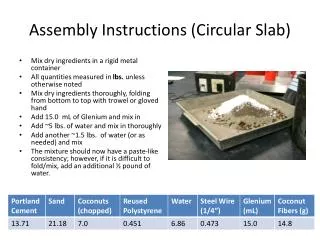
Fixing Kit The fixings needed for the generic pieces of Hive are contained in the bag as shown. Please note as this is a general fixing kit, parts may be left over after assembly.
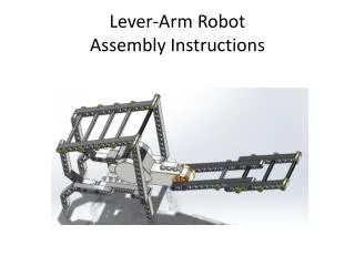
Assembling the Base(straight modules) With the back unit inverted attach the leg rails to the units using the M8 button head bolts.
Assembling the Base(straight modules) With the foot rails attached to both ends of the back, offer up the bench unit and secure with M8 button head bolts. The unit can now be placed upright and stored to one side. Complete this for all the straight pieces.
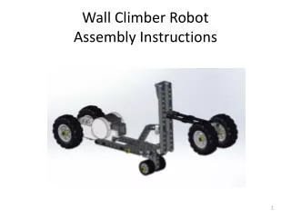
Assembling the Base(corner modules) With the unit inverted attach the leg rails to the units using the M8 button head bolts.
Connecting Modules Together Secure the bench and back section together using the M8 Button head bolts. Secure the bench and back section together using the M8 Button head bolts.
Connecting Modules Together Take the linking pieces from the fixing kit and position under the piece in line with the foot. Offer the joining unit to the piece and secure firmly in the linking device.
Connecting Modules Together Make sure that the joined pieces are level on the seats and backs. If not then the linking devices may not be fully engaged. Complete linking the units around until the configuration is complete.
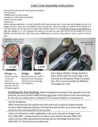
Attaching the Workrails Insert the screen supports into the glides. Note that the arrow on the support needs to point downwards. When in position, the support will click into place.
Attaching the Workrails Place the tool rail over the screen supports. Where two Workrailsare being joined insert a 20mm Work rail linking piece. From either side of the screen supports insert the “U” shape bracket to align the Workrail with the screen support and linking piece.
Connecting Modules Together When aligned loosely, pass a bolt through from one “U” bracket to the other side. Secure this with a bolt and tighten to pull the Workrails together.
Connecting Modules Together The end cap is secured by positioning the two prongs into the screen support and aligning with the Workrail. The end cap is secured in place by using the two tap tite screws that are in the fixing kit. If using the work rail to support accessories or IWS tables, then place the Workrail plate in channel before securing the end cap.
Attaching accessories or IWS tables When attaching Tables to the Workrail, a (included) flexi Pin, should be secured to the plate before inserting into the Workrail. The IWS table top should then be offered up to the Workrail, and the pins inserted into the predrilled holes on the side of the top.
Attaching accessories or IWS tables The cam and pin are secured from the underside of the IWS table top to secure the top and Workrail together. If a column is supplied, this can be adjusted by rotating the base plate to ensure that it is level and the table supported correctly.
Attaching screens The screens are fitted by lowering them down over there respective screen support. To secure the screens a custom fitted piece is already attached in the base and this will engage with the screen support with a click when in the correct position. When the complete configuration has the screens attached the unit will be fully fixed together and cannot be moved.